perating and Installation
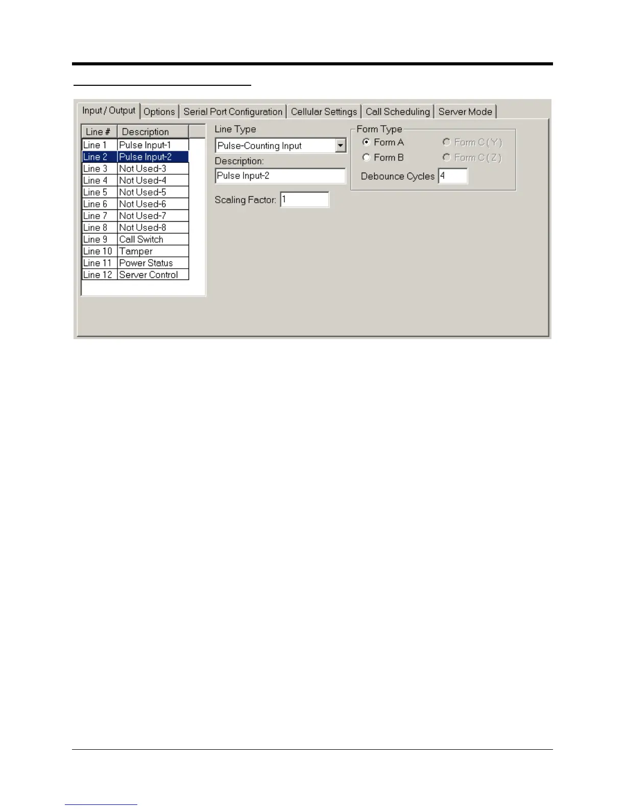
Counting Input Parameters
Configuration of a Pulse Counting Input
is for your records only and
is not reported to the data collection system.
If the input is a normally
. If the input is a normally
. If you are combining Lines
er to create a KYZ input,
one line then the next line will automatically be assigned as the other Form
inherit the partner’s settings. Allowed F
” setting, in combination with the “Sample Rates” setting on the OPTIONS
screen determines how long the switch needs to be closed or open before being considered a
Debouncing and sample rates are discussed in more detail later in this
” is not currently supported.
has the capacity to save a total of 30,000
records before it starts to
overwrite the oldest record
s. These are divided equally between all active pulse
channels. If only one channel is used for pulse
channels are active then each channel is allocated

 Loading...


