perating and Installation
There are a total of six digital sign
board that can be used as alarms, status
counting inputs or control outputs. A later portion of this chapter provides a
technical discussion about how each input is processed.
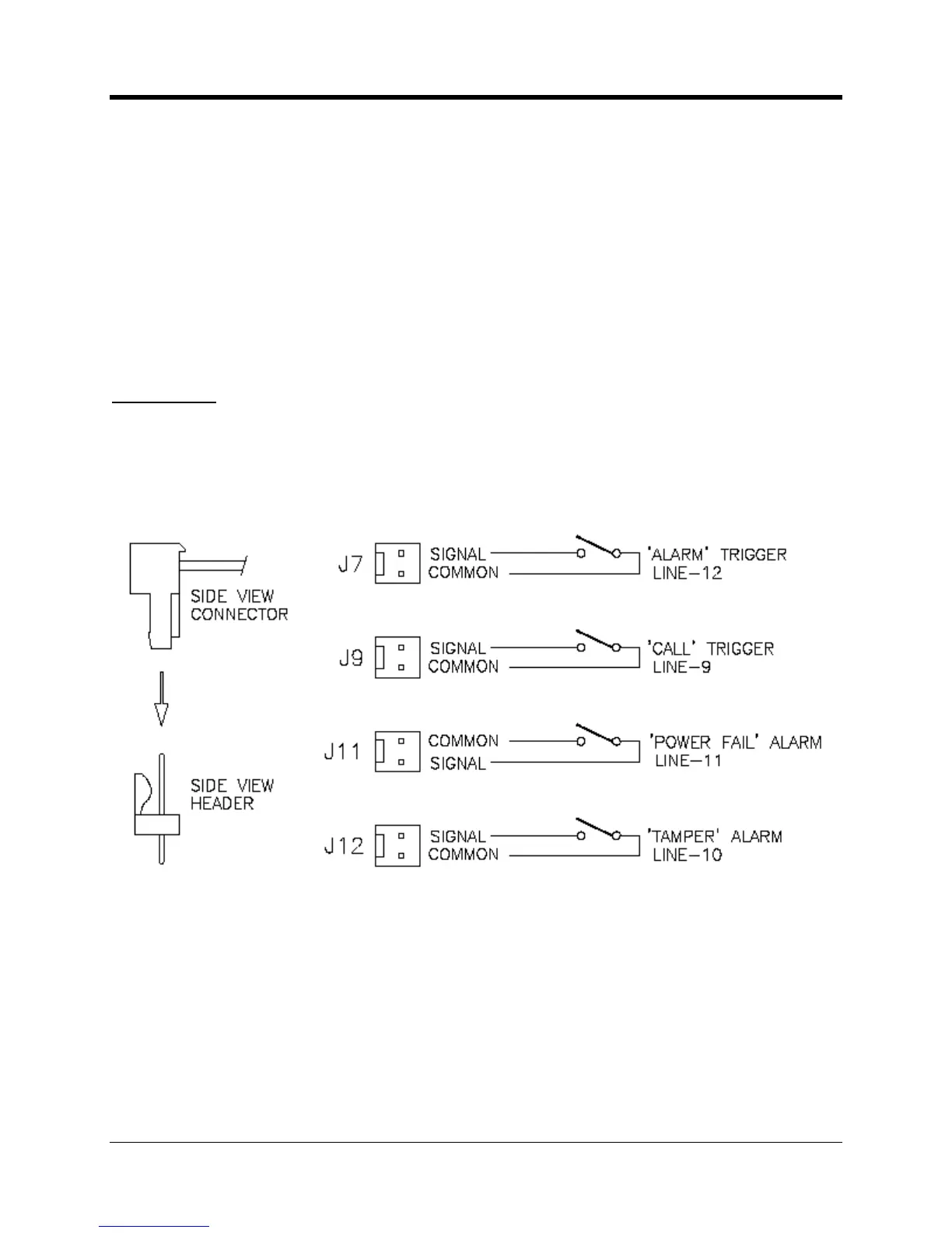
Each signal has a “Line Number” associated with
it as seen in the next figure. Knowing which
line number correlates with which input signal is necessary when using the MP32 configuration
software. In most applications these lines are preconfigured for the most common data logger
channel pulse recorder with power supply control and
monitoring. However any of the six signals can be reconfigured as necessary for the
Any of the six signals can be used as alarms or status inputs. These can be
Two of these inputs are connected to the TB4 terminal block and the other
four have their own connectors. If any input is configured as an alarm or status input then it
cannot be used to count pulses.
1: The common or ground circuit connection at J11 is on the opposite pin when compared
to the other three connectors.
2: Mating connector type is available from AMP/Tyco Electronics under part number
ations of the CNI2 are pre
wired at the factory with a door
switch at J12 and a magnetic call switch at J9.

 Loading...


