perating and Installation
There may be situations in which the device connected to the serial port is sending data at a
volume that exceeds the CNI2’s capacity to process it and pass it on t
In packet mode the data from the serial device is assembled into a “packet”, then sent on to the
central computer. A packet cannot be larger than 1100 bytes and each packet’s arrival at the
central computer must be verified bef
ore another can be sent. Due to latency in the cellular
networks and on the Internet each exchange may take several seconds to complete. During
this time it may be necessary to stop the serial device from sending any more information. The
Some devices do not support any kind of handshaking and may have large messages to send.
This is not usually a problem in CSD mode because each byt
e is immediately sent to the central
computer. In packet mode when the user
defined packet size is reached it is sent to the server.
Meanwhile the data that continues to be transmitted by the serial device is stored in memory.
After the previous packet
has been sent another is collected, packaged and sent.
packet is delivered to the server
However, it is possible for the serial device to eventually overrun the memory if the packets are
w to be delivered to the server. This may lead to the loss of data. One possible solution is to
reduce the baud rate between the serial device and the CNI. This may give the
time to deliver packets and keep up with new data.
ral methods commonly used to control the flow of data between serial devices,
generally called “handshaking”.
. Other selections are for other applications and should not be used.
handshaking uses additional signals on the hardware interface to stop and start the
’s terminal block is an output signal called DSR.
This signal would normally be connected to the “C
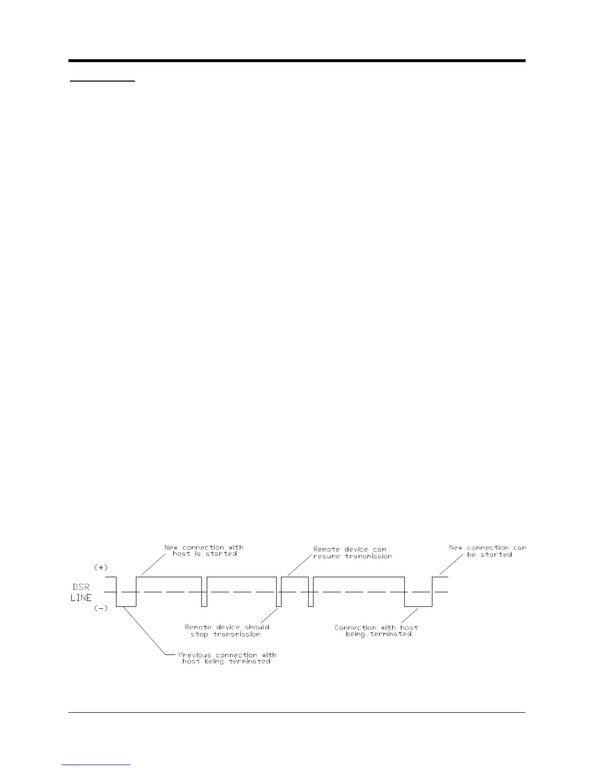
. Initially the DSR line will be positive. A positive voltage on this line indicates that the
may transmit data. When DSR goes negative, the
en the connection is terminated the DSR line will go negative for a brief
moment and then go positive until the next connection.

 Loading...


