Parameters accessible with Function Code 03, 06,10h
Custom map parameters
92 HC900 Process Controller Communications User Guide Revision 13
April 2017
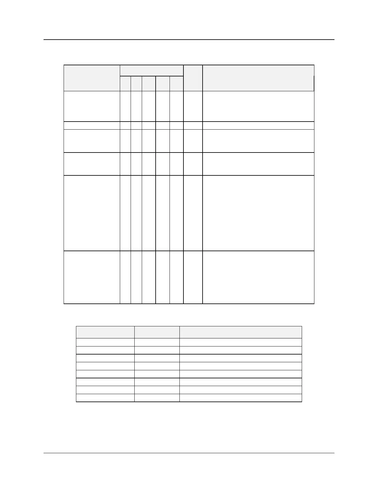
Table 6-28 Custom map Loop parameters
0 – disable
1 – limit cycle
2 – SP tuning
Float in the range of 5% to 15%
PV Adabtive
Enable/Disable
0=Tune Not Ready or in Wait State
1=Tune Ready
2=Tune Running
3=Failed Process Identification – SP Tune
4=SP Error – SP Tune
5=Bad Kpg – SP Tune
6=Failed Output Limit – SP Tune
7=Failed Minimum PV – SP Tune
8=PV Adaptive Running
9=Tuning Aborted
AutoManual
LocalRemote Mode
0.0 = LSP MAN
1.0 = LSP AUTO
2.0 = RSP AUTO
4.0 = LSP IMAN or RSP IMAN
5.0 = LSP LO or RSP LO
6.0 = RSP_MAN
Table 6-29 Custom map Push Button and Four Selector Switch parameters
Integer: Write 1 to “push” the button
Integer: Write 1 to “push” the button
Integer: Write 1 to “push” the button
Integer: Write 1 to “push” the button
Integer in the range of 1 to 4
Integer in the range of 1 to 4
Integer in the range of 1 to 4
Integer in the range of 1 to 4

 Loading...


