EasyManua.ls Logo

Honeywell HC900 - Table 4-6 DI;DO Address Map (Firmware Version 2.3 and Earlier, 16 Channels Max); Table 4-7 Rack #1 DI;DO Address Map (V2.3 and Earlier, up to 16-Channel)

Honeywell HC900
112 pages
To Next Page IconTo Next Page
To Previous Page IconTo Previous Page
Loading...
Modbus/TCP & Modbus RTU Function Codes
Function Code 01 – Read Digital Output Status
26 HC900 Process Controller Communications User Guide Revision 13
April 2017
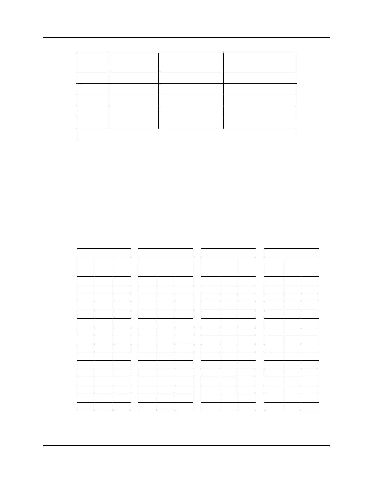
Table 4-6 DI/DO Address Map (Firmware version 2.3 and earlier, 16 channels max)
Rack
Channels
Coil number/
Register number
Modbus Hex
Address Range
1*
1 - 256
1 256
0 - FF
2
257 - 512
257 - 512
100 - 1FF
3
513 - 768
513 768
200 - 2FF
4
769 - 1024
769 1024
300 - 3FF
5
1025 - 1280
1025 - 1280
400 - 4FF
*See Table 4-7 for detailed addresses of Rack #1
The coil (register) number for a digital I/O is based on the DI/DO’s position in the card cage. It is
determined from the formula:
Coil (register) Number = [(Rack-1)*256] + [(Slot-1)*16] + channel in module
Example: To monitor a coil (register) located in the 2nd channel of slot 10 of rack 3, the Modbus coil
(register) number is:
[(3-1)*256] + [(10-1)*16] + 2 = 658
Some third party software packages will require the 1-based coil/register number to be used for the address
while others will require the 0-based hex address.
Table 4-7 Rack #1 DI/DO address map (v2.3 and earlier, up to 16-channel)
Slot 1
Slot 2
Slot 3
Slot 4
CH#
Coil/
register
Addr.
Hex
CH#
Coil/
register
Addr.
Hex
CH#
Coil/
register
Addr.
Hex
CH#
Coil/
register
Addr.
Hex
16
16
0F
16
32
1F
16
48
2F
16
64
3F
15
15
0E
15
31
1E
15
47
2E
15
63
3E
14
14
0D
14
30
1D
14
46
2D
14
62
3D
13
13
0C
13
29
1C
13
45
2C
13
61
3C
12
12
0B
12
28
1B
12
44
2B
12
60
3B
11
11
0A
11
27
1A
11
43
2A
11
59
3A
10
10
9
10
26
19
10
42
29
10
58
39
9
9
8
9
25
18
9
41
28
9
57
38
8
8
7
8
24
17
8
40
27
8
56
37
7
7
6
7
23
16
7
39
26
7
55
36
6
6
5
6
22
15
6
38
25
6
54
35
5
5
4
5
21
14
5
37
24
5
53
34
4
4
3
4
20
13
4
36
23
4
52
33
3
3
2
3
19
12
3
35
22
3
51
32
2
2
1
2
18
11
2
34
21
2
50
31
1
1
0
1
17
10
1
33
20
1
49
30

Table of Contents

Other manuals for Honeywell HC900

Related product manuals