Modbus/TCP & Modbus RTU Function Codes
Function Code 01 – Read Digital Output Status
Revision 13 HC900 Process Controller Communications User Guide 21
April 2017
Digital I/O Channel to Address Mapping
If you have any 32-channel DI/DO modules or if you have firmware version 2.4 or higher you must use the
newer maps in Table 4-4 and Table 4-5. However, use the older maps in Table 4-6 and Table 4-7 if:
Your controller is firmware version 2.3 or earlier or
You have already mapped out 16-channel DI/DO, have no 32-channel DI/DO modules, and don’t
want to change to the newer map.
Note: Up to 16 slots are accommodated in the protocol even though the largest rack available supports 12
slots.
Each DI/DO consumes 1 Modbus bit address.
Decimal addressing is typically non-zero based for DI/DO access (1-based), applicable to coil or register
address.
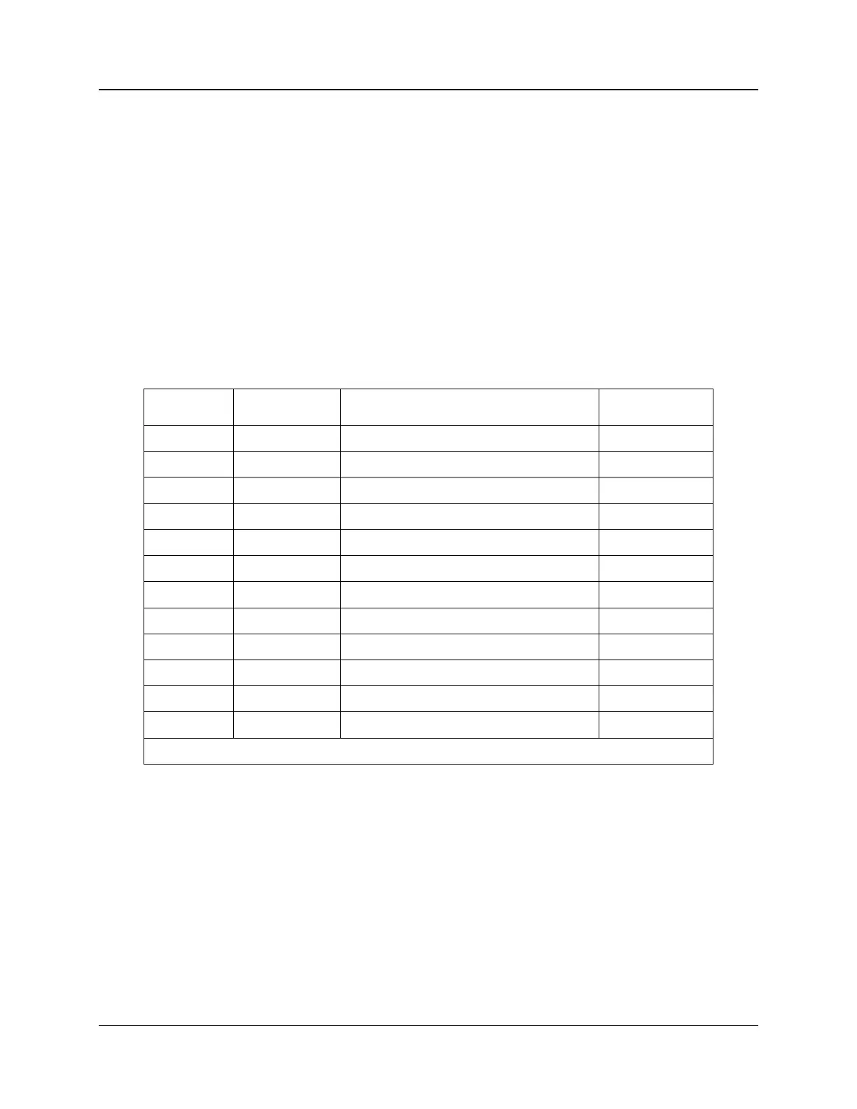
Table 4-4 DI/DO Address Map (v2.4 and higher, up to 32-channel)
Coil number/register number
*See Table 4-5 for detailed map of Rack #1
The coil (register) number for a DI/DO is based on the DI/DO’s position in the card cage. It is determined
from the formula:
Coil (register) Number = [(Rack-1)*512] + [(Slot-1)*32] + channel in module + 2000
Example: To monitor a coil (register) located in the 2nd channel of slot 10 of rack 3, the Modbus coil
(register) number is:
[(3-1)*512] + [(10-1)*32] + 2 + 2000 = 3314
Some third party software packages will require the 1-based coil/register number to be used for the address
while others will require the 0-based hex address.

 Loading...


