Parameters accessible with Function Code 03, 06,10h
Loop Values
Revision 13 HC900 Process Controller Communications User Guide 49
April 2017
6.4 Loop Values
About loop addresses
This table contains fixed addresses of Loop #1. See Table 6-1 for starting and ending fixed addresses
(hex) for Loop #2 through Loop #32. Each successive control loop is offset by 256 with the exception that
loop 25 has a new starting address and loop 26 – 32 are offset by 256. The loop number corresponds to the
PID block entry sequence during Process Control Designer configuration. The Modbus loop number
address for a loop can also be obtained from the Process Control Designer printout of Block Modbus
Addresses.
The addresses given in Table 6-3 do not necessarily apply to loops in the custom map. For custom
addresses view or print a report in HC Designer.
Function Code Support:
Reads – Function Code 3
Writes – Function Code 16 (10 hex) for preset of multiple registers (e.g., for floating point )
Writes – Function Code 6 for presetting an integer value
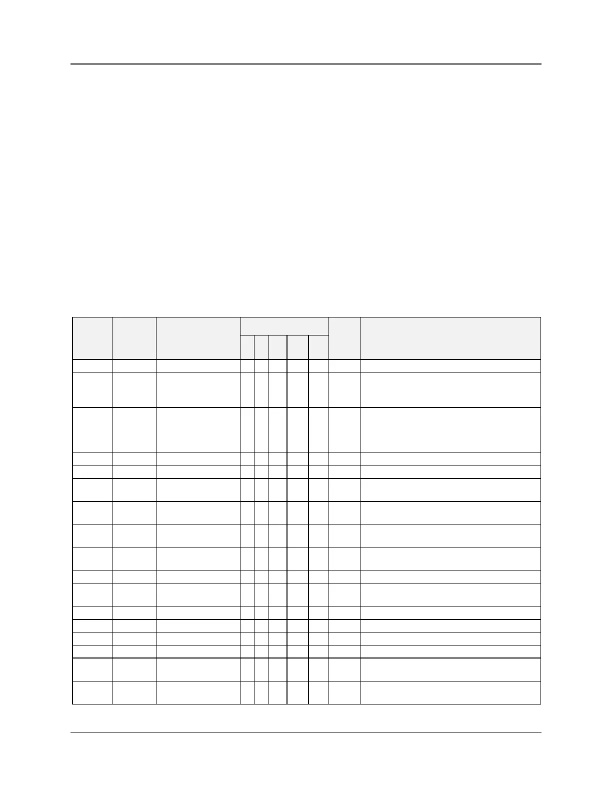
Table 6-3 Loop Values
Floating Point in Engineering Units.
Floating Point in Engineering Units.
When the remote setpoint source is configured as
LSP2, the value can be written.
Floating Point in Engineering Units.
On a write to this register the instrument will update
the proper set point according to the loop’s
currently selected set point.
Floating Point in Engineering Units.
Floating Point in Engineering Units.
Carbon Potential block
temperature
Floating Point in Engineering Units
Gain #1 (Prop Band
#1 if active)
Floating Point . (in units per what was configured in
the HC900: Gain or Proportional Band)
Floating Point
0.0=Direct; 1.0=Reverse
Floating Point in Repeats/Minute or
Minutes/Repeat.
Floating Point in Minutes
Cycle Time for Analog
Scan
Floating Point in Seconds
Floating Point in Engineering Units.
Floating Point in Engineering Units.
Floating Point in Engineering Units.
Floating Point in Engineering Units.
Gain #2 (Prop Band
#2 if active)
Three Position Step
Motor Deadband
Floating Point in percent

 Loading...


