Modbus Double Register Format
IEEE Floating Point Data Format
10 HC900 Process Controller Communications User Guide Revision 13
April 2017
3. Modbus Double Register Format
Data that is 32 bits requires 2 sequential registers (4 bytes) to transfer its data. Data of this type includes IEEE 32-bit
floating point, 32-bit signed integer and 32-bit unsigned integer. The stuffing order of the bytes into the two registers
differs among Modbus/TCP hosts. To provide compatibility, the double register format for the HC900 controller is
configurable.
To set the controller’s double register byte order, go to the “Set Controller Network Parameters ” wizard in the
"Controller Utilities Function" section of the Utilities Tab on the Process Control Designer and configure “Modbus
Double Register Format”. This can be done in the RUN mode.
The selections are:
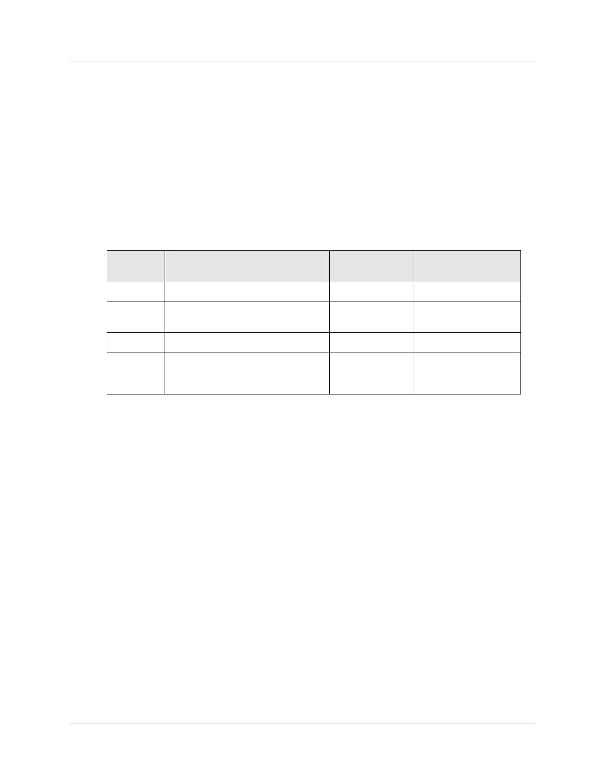
Table 3-1 Modbus Double Register Format Selections
Byte order
(See Figure 2-1)
Floating Point Big Endian Format
Floating Point Big Endian with
byte-swapped
Floating Point Little Endian Format
Floating Point Little Endian with
byte-swapped
Modicon and
Wonderware
standard
See IEEE Formats on page IEEE Floating Point Formats on page 11 and 32-bit integer formats on page 13.
NOTE: Byte Swapping only applies to Function Codes 3, 4, and 16.

 Loading...


