Introduction
Modbus RTU RS232/RS485 Communication Ports
Revision 13 HC900 Process Controller Communications User Guide 5
April 2017
1.3 Modbus RTU RS232/RS485 Communication Ports
This implementation is designed to provide a popular data exchange format connecting the HC900 to both
Honeywell and foreign master devices via the RS232 and RS485 communication ports. The Modbus RTU allows the
instrument to be a citizen on a data link shared with other devices, which subscribe to the Modicon Modbus Protocol
Reference Guide PI-MBUS-300 Rev. G specification.
These instruments DO NOT emulate any MODICON type device. The Modbus RTU specification is respected in the
physical and data link layers. The message structure of the Modbus RTU function codes is employed and standard
IEEE 32-bit floating point and integer formats are used. Data register mapping is unique to the HC900 and other
Honeywell instruments. Section 6 describes the parameter mapping for the HC900.
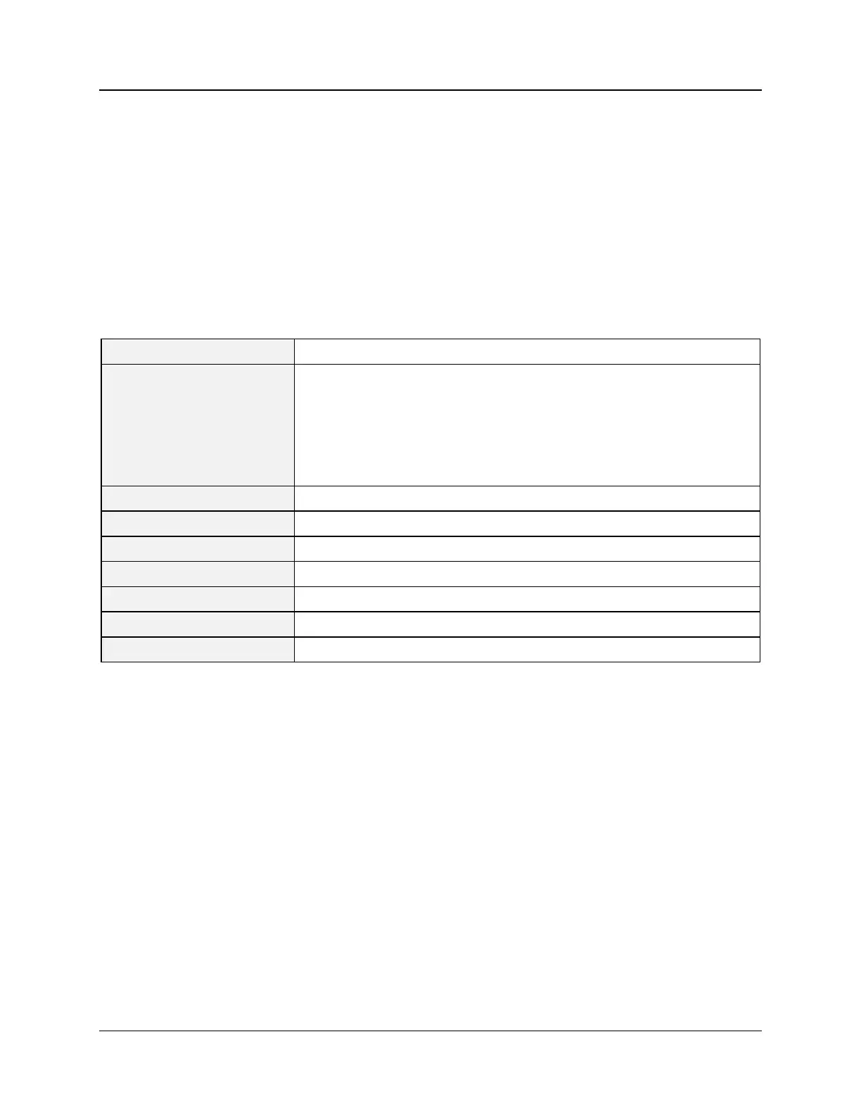
Modbus RTU Message Format
Table 1-1 Modbus RTU Message Formats
Number of data bits per
character
start bits - 1
data bits - 8
parity bits – 0 or 1 selectable
stop bits – 1 or 2 selectable
None, odd, even selectable
1200, 2400, 4800, 9600, 19200, 38400, 57600 Selectable
Half duplex Transceiver or TX/RX
CRC (cyclic redundancy check)
Idle line for 3.5 or more characters (>1.82 msec for 19200).
Modbus RTU Link Layer
The link layer includes the following properties/behaviors:
Slave address recognition,
Start / End of Frame detection,
CRC-16 generation / checking,
Transmit / receive message time-out,
Buffer overflow detection,
Framing error detection,
Idle line detection.
Errors detected by the physical layer in messages received by the slave are ignored and the physical layer
automatically restarts by initiating a new receive on the next idle line detection.

 Loading...


