Parameters accessible with Function Code 03, 06,10h
Signal Tags
64 HC900 Process Controller Communications User Guide Revision 13
April 2017
6.9 Signal Tags
Summary
Signal tags are connected to output pins of function blocks, representing analog or digital parameters, and
are read-only parameters. Digital Signal tags are also represented in floating point, 0.0 for OFF or logic 0,
1.0 for ON or logic 1. The signal tag number in Table 6-11 corresponds to the signal tag number in the
HC900 Process Control Designer configuration. You will need to access the Process Control Designer
configuration "Tag Information" report to identify the Signal Tag numbers desired.
Note: to convert floating point values (analog or digital) to integer 16, (for use with third party touch panels
and associated HMI software, for example), use the user-defined signals and variables for assigning new
Modbus addresses and associated data type, configurable in HC Designer, Ver. 2.0 or later.
Function Code Support:
Read – Function Code 3
NOTES:
Floating Point in Engineering Units
Digital Signal Tags are represented as 0.0 for OFF, 1.0 for ON.
Access is Read Only
Signal tags 1-1000 have two addresses each; one for legacy use and one for HC900. For
example, signal tag #1 is at hex addresses 2000 and 3B60.
The addresses given in Table 6-11 do not necessarily apply to signal tags in the custom map. For custom
addresses view or print a report in HC Designer.
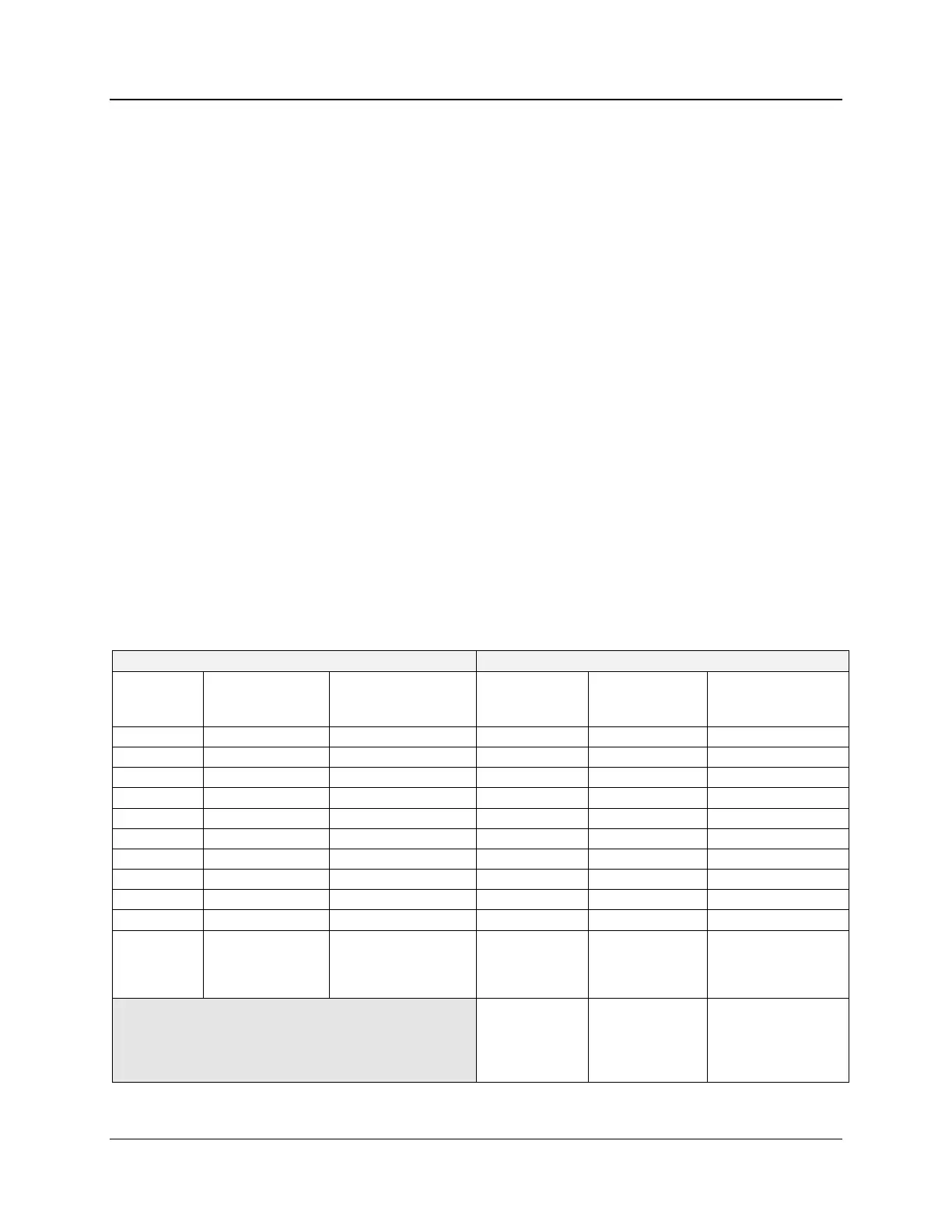
Table 6-11 Signal Tags
Signal tag #1001
.
.
.
Signal tag #4000

 Loading...


