FireWarden 100-2/E — P/N 52778:A 11/04/2005 17
Components Product Description
✓
12 Tone Burst types: 20 pps
(3+1, 4+1, 4+2, 3+1 Exp., 4+1 Exp., 4+2 Exp.)
✓ 3 Touchtone Types
4+1 Ademco Express
4+2 Ademco Express
Ademco Contact ID
1.6 Components
Main Circuit Board
The main circuit board contains the system’s CPU, power supply, other primary components and
wiring interface connectors. The 4XTM option module plugs in and is mounted to the main circuit
board.
Cabinet
The NFW2-100 backbox provides space for two batteries (up to 18 Amp Hour). Ample knockouts
are provided for system wiring. Also available is an optional dress panel (DP-9692B), which
mounts to the inside of the cabinet. The dress panel must be installed to meet FM requirements.
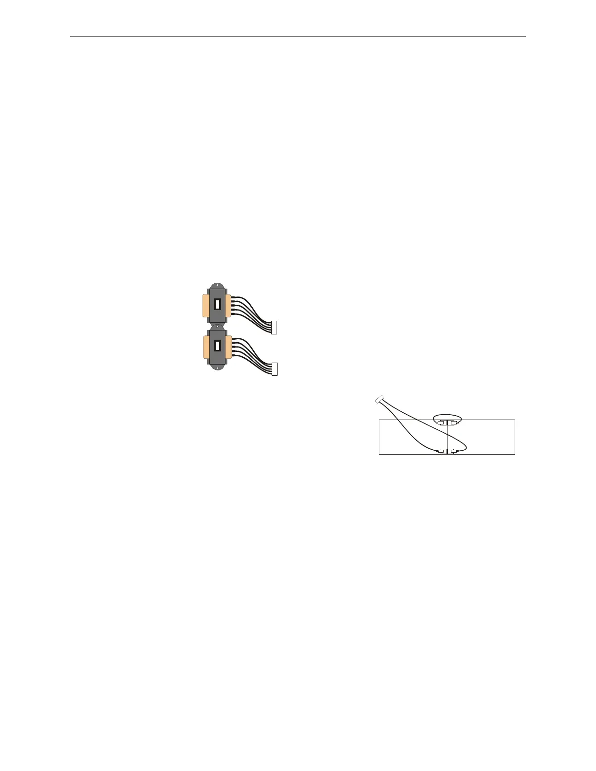
Transformer Assembly
One 100VA transformer is provided standard with the
panel (3.6 amps maximum). An optional 100 VA
transformer XRM-24 (XRM-24E for the NFW2-100E) is
available to provide maximum system and accessory power
(6.6 amp total).
Batteries
The NFW2-100 cabinet provides space for two batteries
(up to 18 Amp Hour). Batteries larger than 18 Amp Hour
require an external charger such as the CHG-75 or CHG-
120 and a UL listed battery box such as the NFS-LBB.
Batteries must be ordered separately.
1.6.1 Intelligent Addressable Detectors
Intelligent, addressable detectors provide information to the control panel on an SLC Signaling
Line Circuit (refer to the FireWarden SLC Wiring Manual for detailed information on device
installation, wiring and operation). This allows the control panel to continually process the
information to determine the status (alarm, trouble, maintenance or normal) of each detector. Each
detector responds to an SLC address that is set in the detector head using built-in rotary decimal
switches. The maximum address cannot exceed address 99. Note that a blinking LED on an
intelligent detector indicates communication between the detector and the control panel.
These devices can operate in CLIP mode (Classic Loop Interface Protocol) or LiteSpeed mode to
provide a quicker response. Refer to the FireWarden SLC Wiring Manual for a list of compatible
addressable detectors.
1.6.2 Intelligent Addressable Modules
Control Modules and Monitor Modules provide an interface between the control panel and
conventional notification and initiating devices. Each module can be set to respond to an address
with built-in rotary switches. The maximum address cannot exceed address 99. Note that a
blinking LED on an addressable module indicates communication between the module and the
control panel.
Standard
XRM-24(E)
Optional
XRM-24(E)
9200xfor.cdr
-
-
+
+
Battery Cable P/N 75287
9200batt.cdr
 Loading...


