36 FireWarden 100-2/E — P/N 52778:A 11/04/2005
Installation Optional Module Installation
6. When the installation has been complete, enable the 4XTM module by sliding the disconnect
switch to the left
7. Test system for proper operation
2.9.2 Printer/PC
A serial printer or a PC (personal computer) may be connected to TB8 Terminals 1 - 4 on the FACP.
The printer can be used to provide a hard-copy printout of real-time events, history file and walktest
data. An IBM compatible PC can be connected to provide local FACP programming capabilities
using the VeriFire Warden programming utility. Installation of either device requires panel
programming to allow the FACP to communicate with the device.
Installation
Remote printers and PCs require separate primary power. Also required is the PRT/PK-CABLE
which is an interface cable prewired to a DB9F connector. Wire the PRT/PK-CABLE to TB8
Terminals 1 - 4 as illustrated in the following figure. Connect the DB9F connector to the printer or
PC serial EIA-232 port. If a nine-pin serial connector is not available on the printer or PC, use a
DB25 adapter. Make certain that the DB25 adapter does not swap the Transmit and Receive lines.
Apply power to the FACP and printer or PC. Note that a ground fault (zero impedance to ground)
may occur on the FACP, dependent on the printer or PC being used, due to this connection. For
this reason, it is important that there be no preexisting ground fault on the panel.
NOTE: Jumper JP2 on the FACP main circuit board can be used to configure the FACP
supervisory relay for operation with the 4XTM module. Relay 3 at TB5 must be programmed as a
supervisory relay.
Cutting JP2 will allow the 4XTM to generate a trouble if the supervisory contact opens.
Leaving JP2 in will prevent generation of a trouble if the supervisory contact opens.
RELAY 1
CUT TO
MONITOR
4XTMF
KISSOFF
PRI. ACTIVE
SEC. ACTIVE
SEC. PHONE LINE
PRI. PHONE LINE
4XTMF
RELAY 2
NO NC C NO NC C
B+ A+ B- A- A B
ACS
SHIELDSLC
SLCSLCSLC
OUT+ I N+ OUT- I N-
TB5 TB6 TB8 TB9 TB10
JP1
JP2
JP3
1 2 3
J13 J12
J7
J5
J6
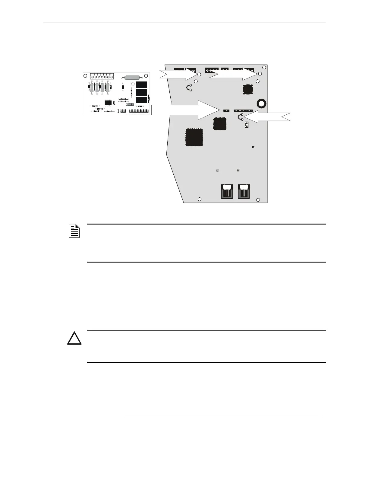
Figure 2.16 4XTM Connectors to NFW2-100 Connectors
J5 & J6 Connectors
Cut Jumper JP3
Standoff Standoff
4XTM
FACP main circuit board
92ud4xtm.cdr
!
CAUTION:
Do not connect a printer or PC to the NFW2-100 FACP if a ground fault (zero impedance to ground)
exists on the control panel. Circuit damage may result. Remove all power (Primary and Secondary)
before installing or removing any wiring.
 Loading...


