32 FireWarden 100-2/E — P/N 52778:A 11/04/2005
Installation UL Power-limited Wiring Requirements
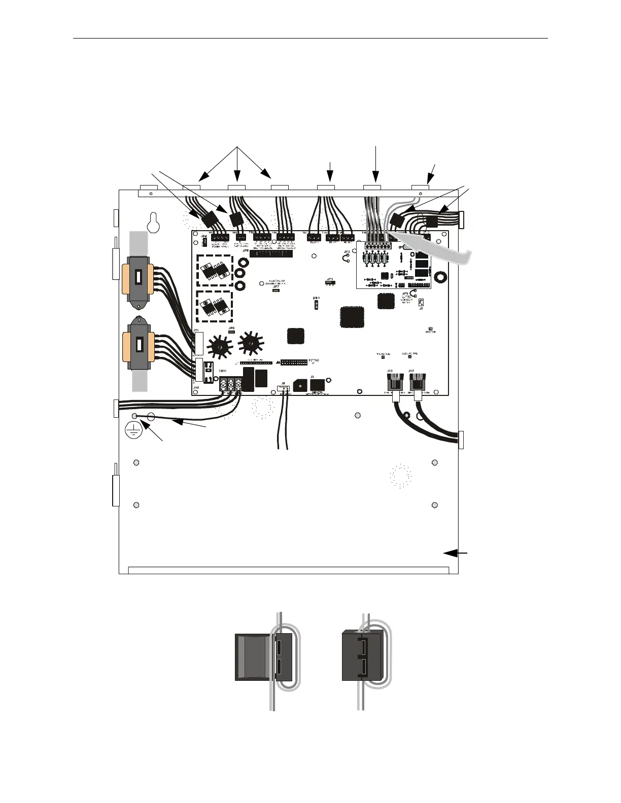
2.7 UL Power-limited Wiring Requirements
Power-limited and nonpower-limited circuit wiring must remain separated in the cabinet. All
power-limited circuit wiring must remain at least 0.25” (6.35 mm) away from any nonpower-
limited circuit wiring and nonpower-limited circuit wiring must enter and exit the cabinet through
different knockouts and/or conduits. A typical wiring diagram for the NFW2-100 is shown below.
Figure 2.11 Typical UL Power-limited Wiring Requirements
Power-limited Circuits
Power-limited Circuits
Nonpower-limited Circuits
Power-limited Circuits
Nonpower-limited
Circuits
AC Power
Grounding Stud
92udulpw.cdr
Nonpower-limited Circuits
To Batteries
maintain minimum
0.25” between power-
limited and nonpower-
limited circuits wiring
Ground Strap
*Ferrite Beads
*Ferrite Beads
Wrap wire around ferrite bead as shown.
Close ferrite bead.
*Ferrite Bead Installation
Per FCC requirements, ferrite beads are required for the DC Power Outputs, Remote Power Supply Sync, ACS Output and SLC
Circuit.
 Loading...


