34 FireWarden 100-2/E — P/N 52778:A 11/04/2005
Installation Optional Module Installation
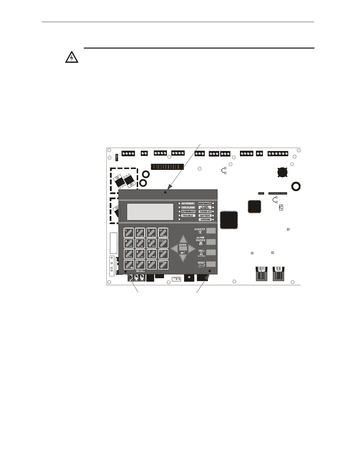
2.9 Optional Module Installation
NFW2-100 Keypad/Display Removal
Removal of the keypad/display is normally not necessary. If, however, it becomes necessary to
replace the keypad/display or access jumpers JP5 and JP7 or switch SW1, the Keypad/Display can
be removed by inserting a Phillips screwdriver into each of the three holes located in the flexible
covering of the Keypad/Display and loosening the three mounting screws. Note that it is not
necessary to disconnect the cables between the Keypad/Display and the main circuit board unless
the unit itself is being replaced. Carefully lift the Keypad/Display and rest the unit at the bottom of
the main circuit board.
2.9.1 4XTM Transmitter Module Installation
The 4XTM provides a supervised output for a local energy municipal box transmitter in addition to
alarm and trouble reverse polarity. A jumper option allows the reverse polarity circuit to open with
a system trouble condition if no alarm condition exists. A disable switch allows disabling of the
transmitter output during testing to prevent accidental calling of the monitoring service.
Local Energy Municipal Box Service (NFPA 72 Auxiliary Fire Alarm Systems):
Supervisory Current: 5.0 mA
Trip Current: 350 mA (subtracted from notification appliance power)
Coil Voltage: 3.65 VDC
Maximum Coil Resistance: 14.6 ohms
Maximum allowable wire resistance between panel and trip coil: 3 ohms
Municipal Box wiring can leave the building
!
WARNING: Disconnect all sources of power (AC and DC) before installing or removing any modules
or wiring.
+ 24V -
NON-RST
POWER
+ 24V -
RST
POWER
REMOTE PWR
SUPPLY SYNC
NAC 1 CLASS A
NAC 1 & 3 CLASS B
NAC 2 CLASS A
NAC 2 & 4 CLASS B
RELAY 3
RELAY 1
HOT NEUT EARTH
- +
BATTERY
LCD DISPLAY
REMOVE TO
DISABLE GND. FLT.
CUT TO
MONITOR
4XTMF
KISSOFF
PRI. ACTIVE
SEC. ACTIVE
SEC. PHONE LINE
PRI. PHONE LINE
4XTMF
MINI DIN
KEYBOARD CONN.
KEYPAD
I/F
RELAY 2
TRANSFORMER 1
TRAN SFORMER 2
+ -
B+ A+ A- B- B+ A+ A- B-
1B+ 3B+ 3B- 1B- 2B+ 4B+ 4B- 2B-
NO NC C
NO NC C NO NC C
B+ A+ B- A- A B
ACS
SHIEL DSLCSLC
SLCSL C
OUT+ I N+ OU T- I N-
TB1
TB2 TB3 TB4 TB7
TB5
TB6
TB8 TB9 TB10
JP4
JP1
JP2
JP3
SW1
JP7
JP5
JP6
1
2
3
1 2 3
TB11
J10
J3
J13 J12
J7
J5
J1
J4
J9
J6
J11
CAUTION!
HIGH VOLTAGE
Figure 2.14 Keypad/Display Removal
Mounting Screw Access Hole
Mounting Screw Access Holes
96dact1.cdr
 Loading...


