3 - 7
Base LED Sequences and Meaning
The base contains a red LED that indicate the status of the unit and verifies
its communication with the host system. The base also has a green LED
that indicates the scanner battery charge condition.
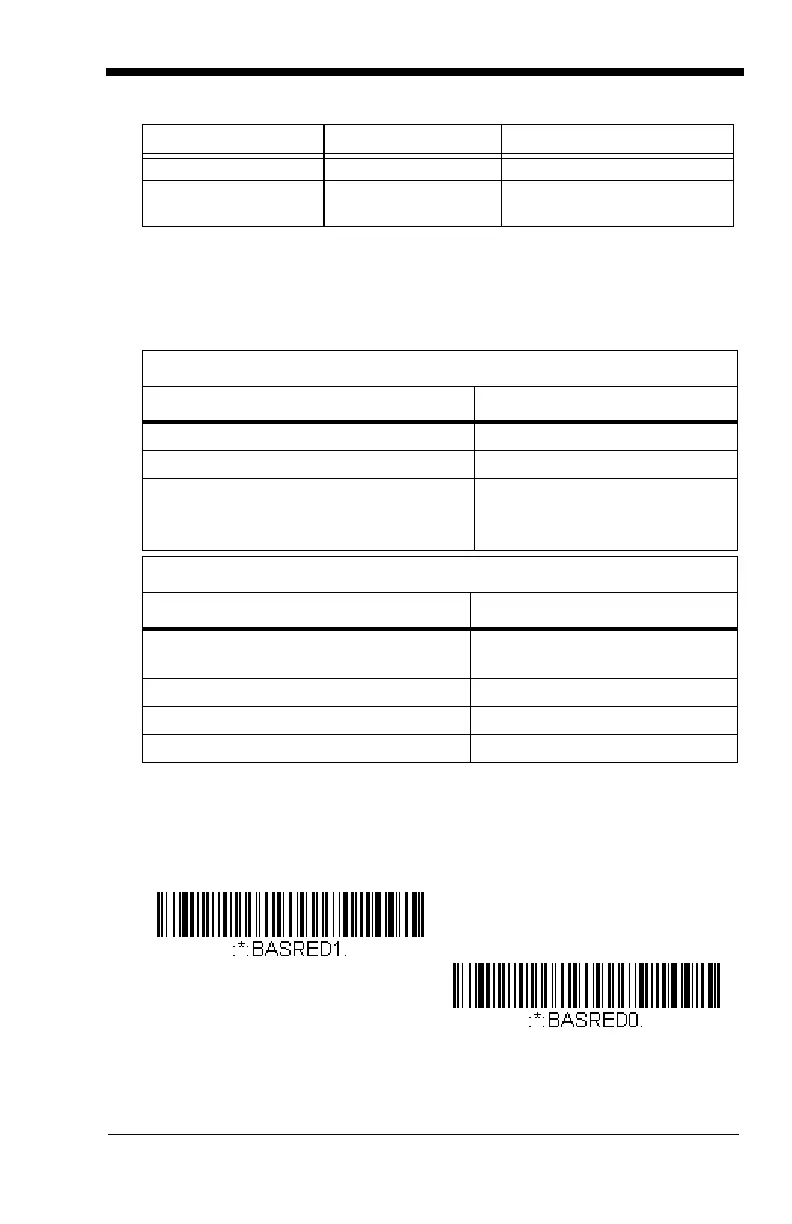
Base Power Communication Indicator
To display the power indicator on the base, scan the Base Power Commu-
nication Indicator On bar code. To turn off the power indicator, scan the
Off bar code.
Default =
On
.
Green Flash 2 beeps Successful menu change
Red, blinking Razz or error tone Unsuccessful menu
change
Red LED - Host Communication
Red LED Communication Condition
Off Power off, USB suspend
On continuously Power on, system idle
Short blinks. Occurs while transferring
data to/from the RF module or the host
port.
Receiving data
Green LED - Scanner Battery
Green LED Charge Condition
Off Battery not detected or charge
suspended
Slow flash, 1 second on, 1 second off Pre-charge and charging
On continuously Charge complete
Fast flash, 300 mSec on, 300 mSec off Charge Error
LED Indication Beeper Indication Cause
* Base Power Communication
Indicator On
Base Power Communication
Indicator Off

 Loading...