5
3. Verify that the power system at the installation site meets the requirements of the power supplies,
including the input method and rated input voltage.
Cooling
Plan the installation site for adequate ventilation.
• A minimum of 10 cm (3.94 in) of clearance is reserved at the inlet and outlet air vents.
• The rack for the switch has a good cooling system.
• The installation site has a good cooling system.
• Verify that the airflow design of the chassis meets the airflow design of the installation site.
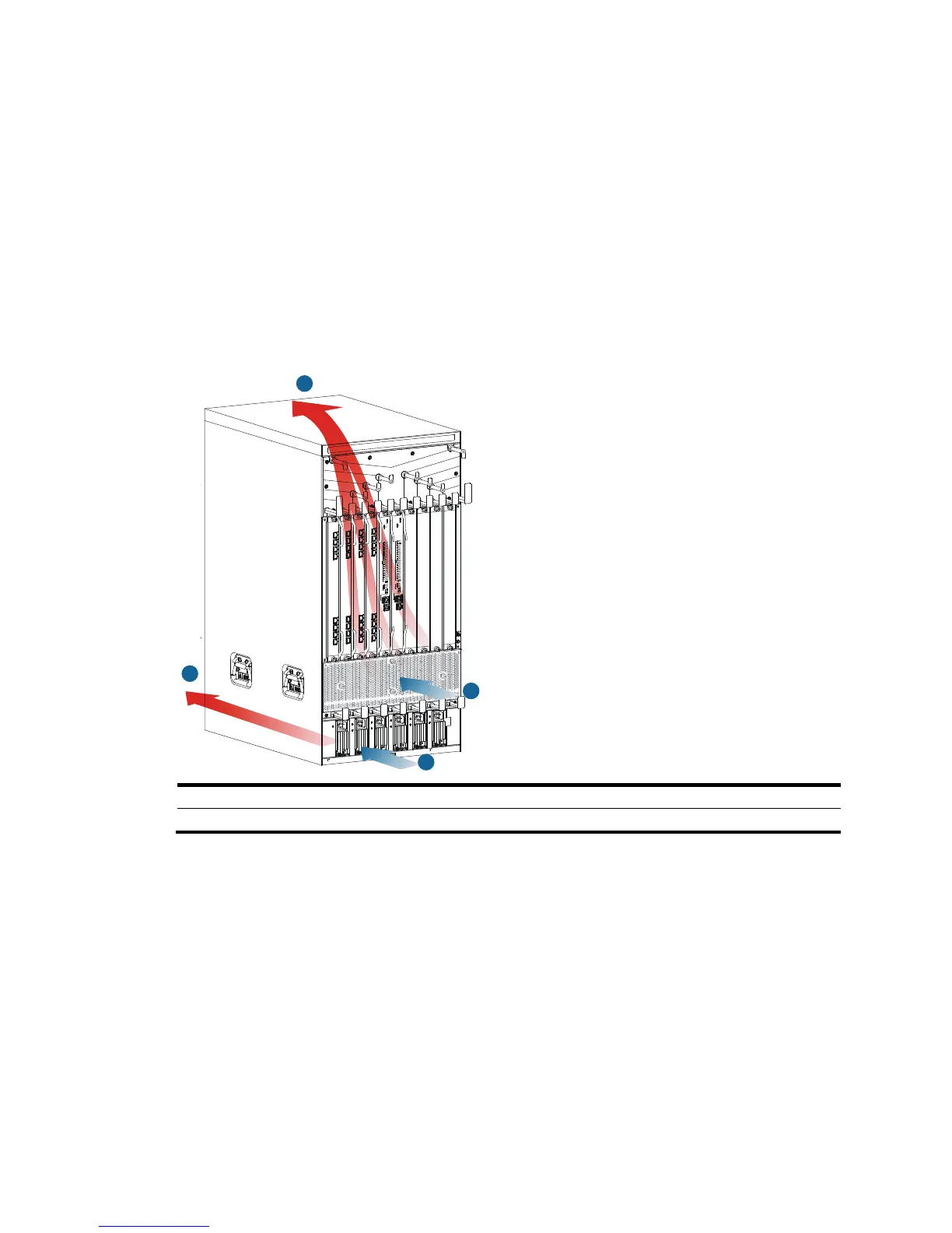
Figure 1 Airflow through the 10508-V chassis
(1) Power supply air intake vents (2) Power supply