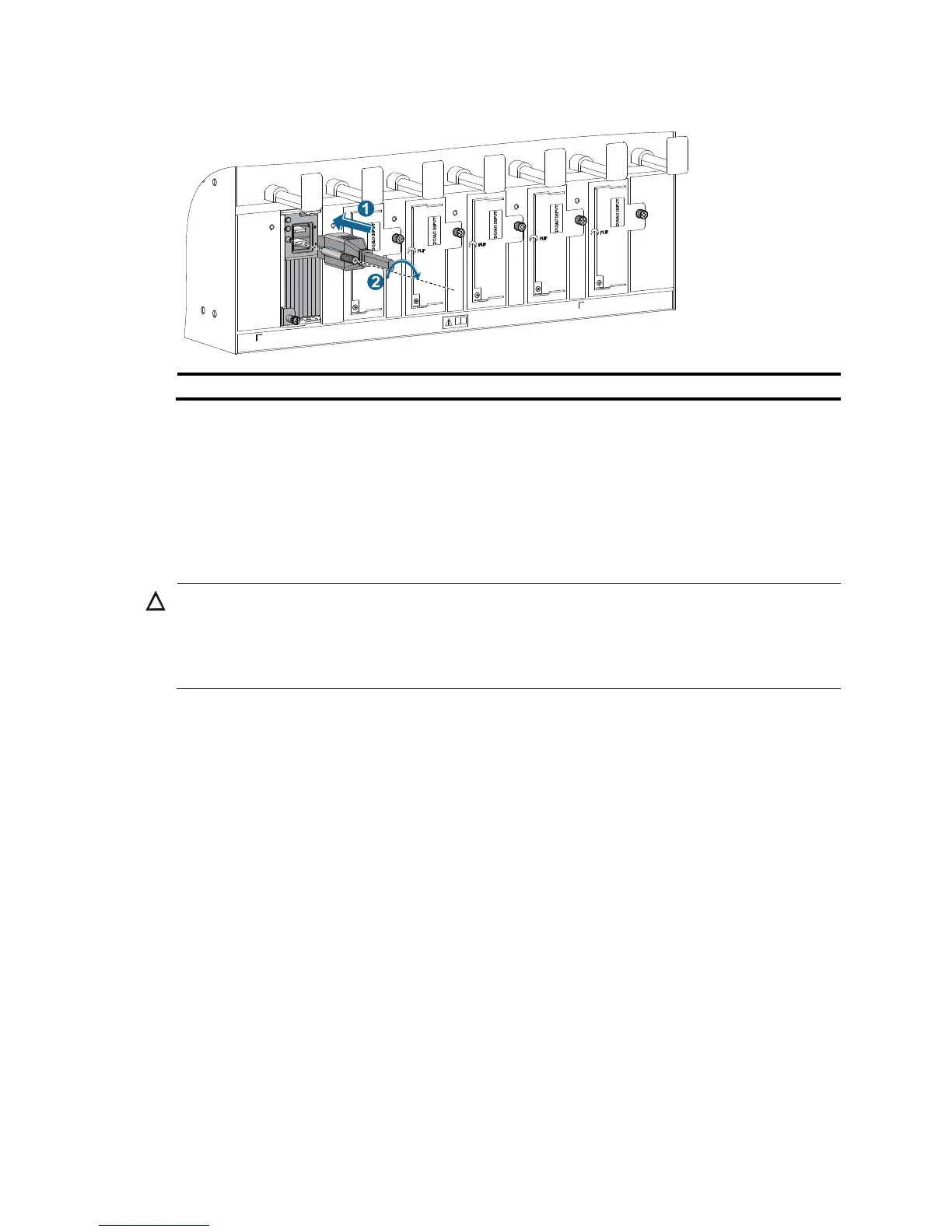
(2) Fasten the screw.
3. (Optional.) Use a cable tie to secure the power cord to the cable management bracket. For more
information, see Figure 23 and Figure 24.
4. Conne
ct one end of the blue DC power cord marked –48V to the negative terminal (–48V) on the
power source and the RTN end of the black DC power cord to the positive terminal (RTN).
Installing a transceiver module (optional)
CAUTION:
• To avoid component damage, read this section carefully before installing a transceiver module.
• Do not remove the protection cover from a transceiver module before connecting an optical fiber.
• Remove the optical fiber, if any, from a transceiver module before installing it.
The transceiver modules available for the switch include SFP, SFP+, XFP, QSFP+, and CFP.
Installing an XFP/SFP+/SFP/QSFP+ module
1. Wear an ESD wrist strap and make sure it makes good skin contact and is reliably grounded. For
more information, see "Attaching an ESD wrist strap."
2. Unpac
k the module. Do not touch the golden plating of the module.
3. Pivot the clasp of the module up. Holding the module, gently push the module into the slot until it
has firm contact with the slot (when the top and bottom spring tabs catch in the slot), as shown
in Figure 26.
{ For a QSFP+ module that uses a plastic pull latch, skip this step. QSFP+ modules use either a
metal or plastic pull latch. They are installed in the same way except that you must pivot the
clasp up for the module that uses a metal pull latch.
{ For an SFP+ module, press the module down against the upward force of the bottom spring tab
so you can push the module straight into the port.
{ If you cannot hold the module by its two sides because of high module density, press the module
on its head end to push it in.