HP 81110/04A Quick Start Getting Started 91
Getting Started
Examples
4. Setting Up an Edge-displacement Signal
NOTE: Two Outputs are required for this example. The channel addition
feature is used for this example. Therefore, this type of signal can
be performed by HP 81104A and HP 81110A with HP 81111A
10V/165 MHz Outputs.
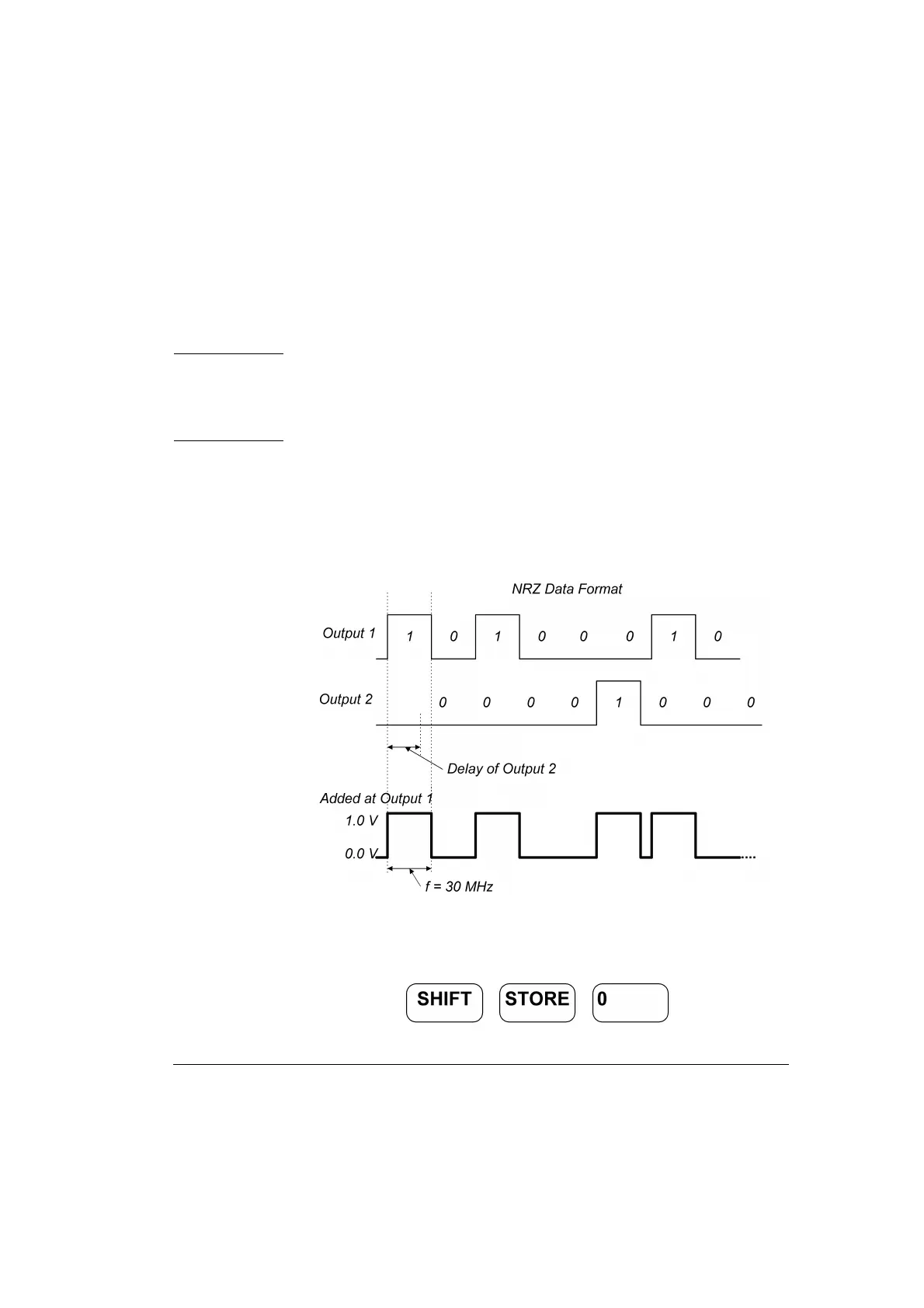
Here a continuous pattern signal, with one distorted pulse will be set up.
The two channels are added with NRZ (Non Return to Zero) pulses at
both outputs, high level of 1 V and low level of 0 V and Channel 2 delay
of 10 ns. The bit frequency is 30 MHz.
Figure 41 Edge-displacement Signal Diagram
1 Before setting up the signal it is recommended to reset all parameters
by pressing .