HP 81110/04A Quick Start Getting Started 97
Getting Started
Examples
5. Setting Up a Dual Clock Signals
NOTE: For this example two Outputs are required.
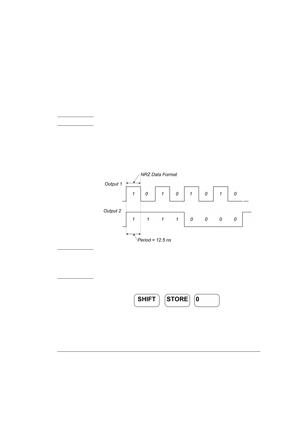
Here a Dual Clock Signal will be set up. In pattern mode with NRZ
(Non Return to Zero) pulses, a period of 12.5 ns and a high level of
2.50 V and a low of 0 V. Output 1 generates a clock signal that is half of
the system clock. Output 2 divides the system clock by 8.
Figure 47 Dual Clock Signal Diagram
NOTE: With an additional dual channel instrument, multiples of these
dual clock signals can be set up following a similar procedure as
follows. For example, with 8 dual channel units up to 16 different
clocks can be generated.
1 Before setting up the signal it is recommended to reset all parameters
by pressing .