Component and LED identification 20
Item Name Description
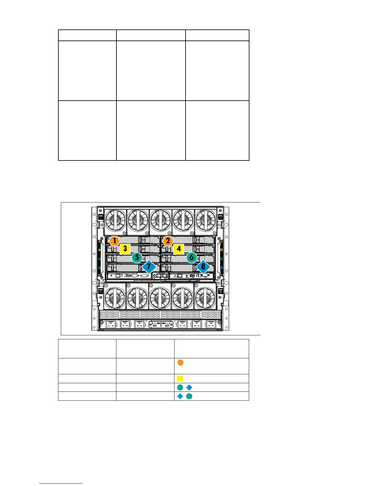
7
Serial connector Serial RS232 DB-9
connector with PC
standard pinout. Connect
a computer with a
null-modem serial cable
to the Onboard
Administrator command
line interface (CLI).
8
VGA VGA DB-15 connector
with PC standard pinout.
To access the KVM menu
or Onboard
Administrator CLI,
connect a VGA monitor
or rack KVM monitor for
enclosure KVM.
Interconnect bay numbering
To support network connections for specific signals, install the interconnect module into the appropriate bay.
Server blade signal Interconnect bay
number
Interconnect bay label
NICs 1, 2, 3, and 4
(embedded)
1, 2
Mezzanine 1
3, 4
Mezzanine 2
5, 6 and then 7, 8
Mezzanine 3
7, 8 and then 5, 6
For information on the location of LEDs and ports on individual interconnect modules, see the documentation
that ships with the interconnect module.
For more information, see "Mapping to interconnect ports (on page 48)."