Removal and replacement procedures 30
•
Install the BBWC into an empty BBWC DIMM socket on any Smart Array 641 or 642 Controller
in the recovery server.
6. Power up the recovery server. A 1759 POST message is displayed, stating that valid data was
flushed from the cache. This data is now stored on the drives in the recovery server. You can now
transfer the drives (and controller, if one was used) to another server.
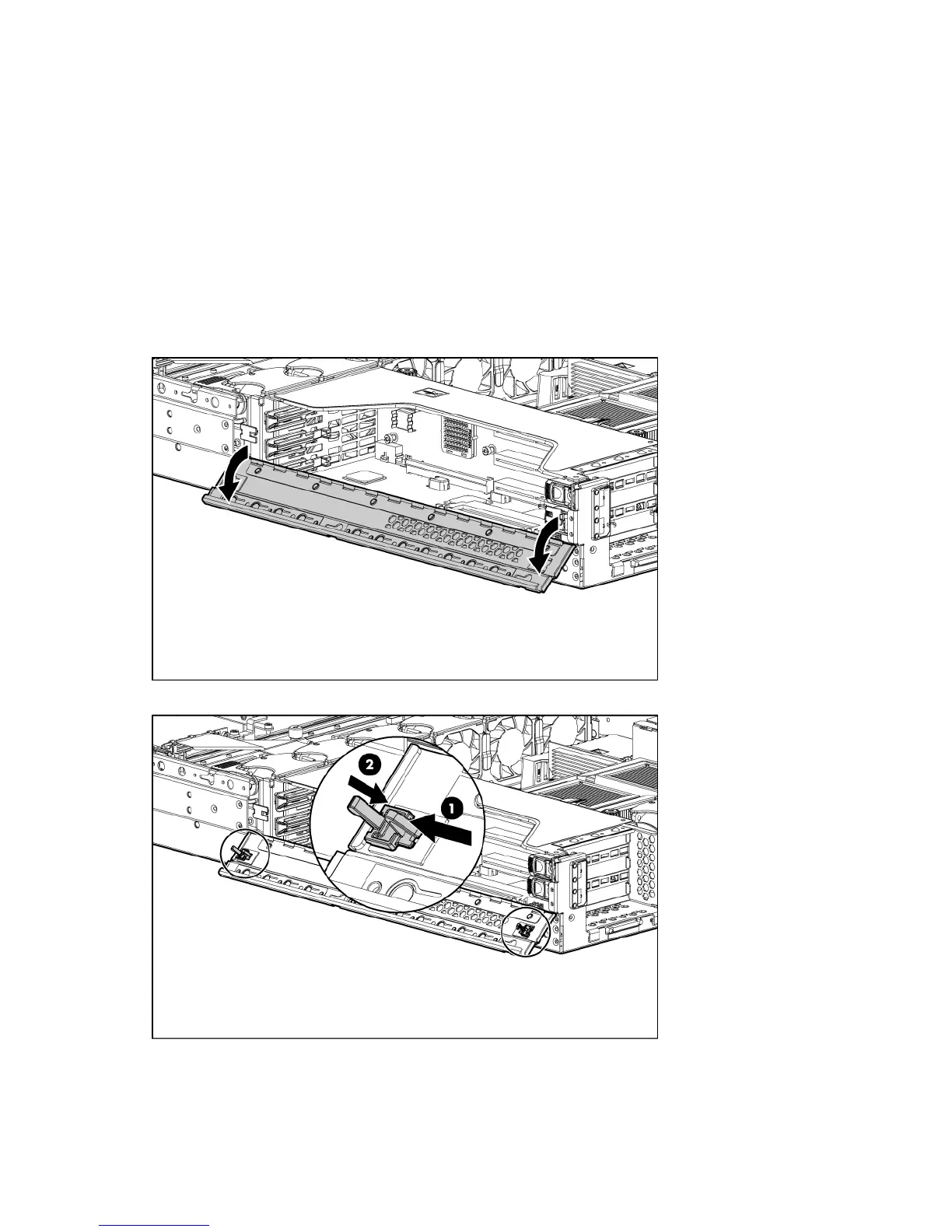
PCI riser cage door latch
To remove the component:
1. Extend or remove the server from the rack ("Extend the server from the rack" on page 19, "Remove
the server from the rack" on page 20).
2. Remove the access panel ("Access panel" on page 22).
3. Open the PCI riser cage door.
4. Remove the PCI riser cage door latch.
To replace the component, reverse the removal procedure.
 Loading...