Enterprise Modular Library E-Series user guide 71
Card cage expansion module power supply
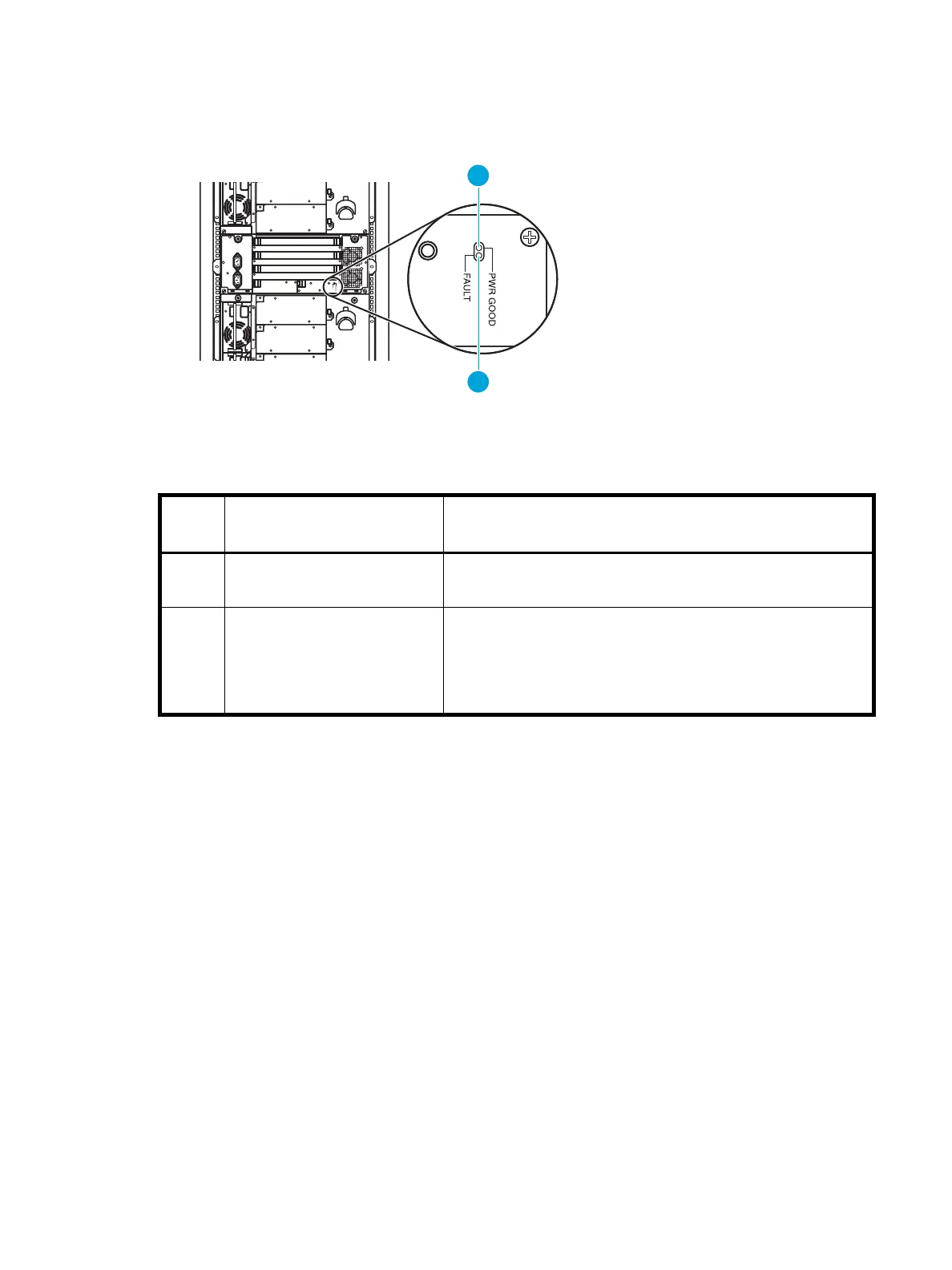
Figure 50 and Table 14 show and describe the function of the indicators located on the power supply in
the card cage expansion module.
Figure 50 Card cage expansion module power supply indicators
Table 14 Card cage expansion module power supply indicators
Index
No.
Control/indicator Function
1 PWR GOOD LED When lit (green), all DC outputs and the AC input is within
operational limits.
2
FAULT LED When lit (amber), one or all of the DC outputs or the AC input is
not within operational limits. This can be an indication that the
module power cord is not fully seated into a power receptacle at
either end, or that the main library power switch has been turned
off.
10450
1
2