Hardware options installation 75
10.
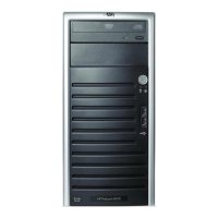
Grab the power supply cables from the RPS backplane assembly and then insert the backplane into
the bay carefully.
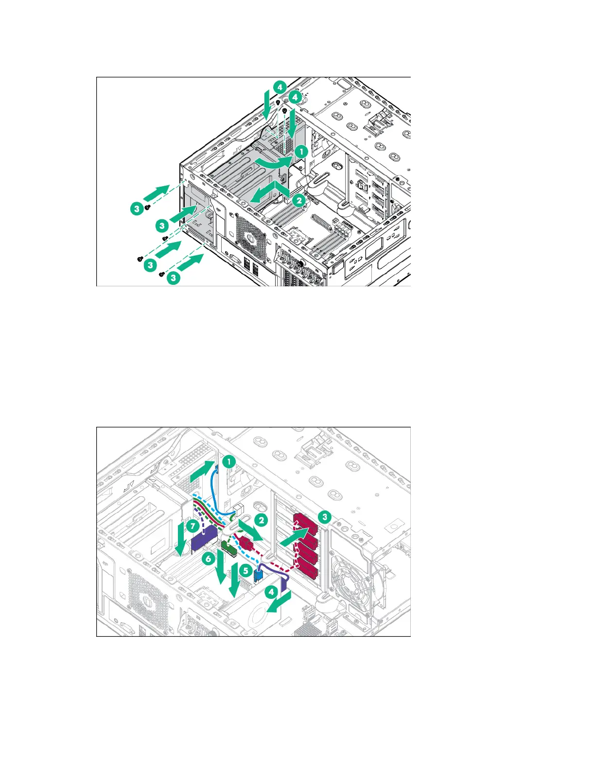
11. Connect the RPS backplane cables and then route the cables underneath the metal tabs:
o 4 LFF non-hot-plug configuration
— Optical drive power cable to optical drive
— 8-pin drive power cable to the non-hot-plug drive power connector
— 4-pin power cable to system board
— 6-pin power cable to GPU, if installed
— RPSU cable to system board
— 24-pin power cable to system board
o 4 LFF and 8 SFF hot-plug configuration
— Optical drive power cable to optical drive
— 8-pin drive power cable to the hot-plug drive backplanes

 Loading...