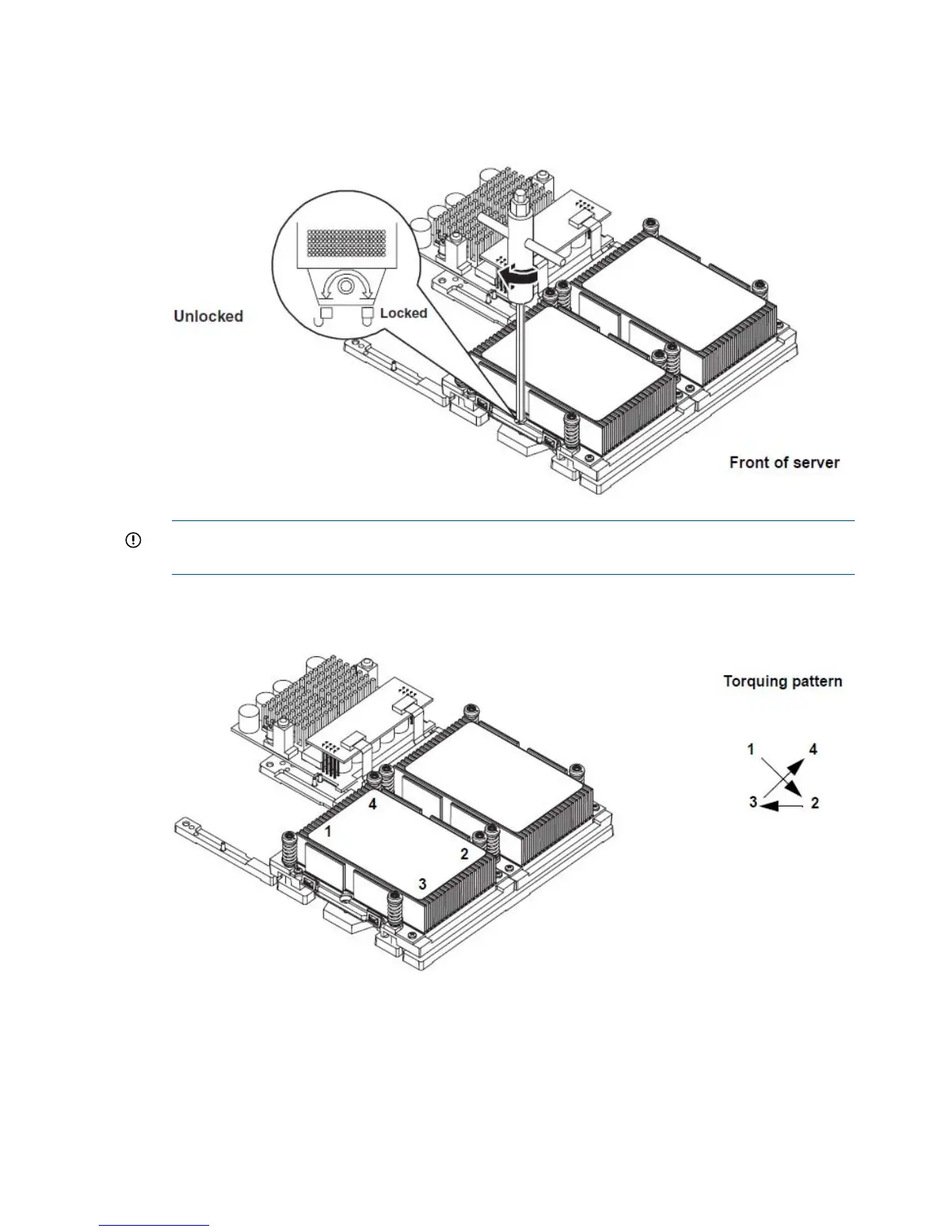
8. Use the special processor tool (P/N 5069-5441) shipped with your replacement processor
assembly to lock the processor in place on the system board. To do this, insert the special
processor tool into the lock and rotate it clockwise 180 degrees.
Figure 8 Locking the Processor Assembly in Place
IMPORTANT: Before proceeding to step 9, make sure the processor is locked in place on
the system board, or the processor will be damaged when the captive screws are tightened.
9. Screw in the four captive screws.
Figure 9 Installing the Processor
10. Slide the power module on the system board metal mounting bracket forward to mate the
power module connector with the processor connector.
14 Installing and Configuring

 Loading...


