Cabling
Cabling overview
This section provides cabling diagrams. When you are cabling the system, refer to the appropriate section based on your
system configuration. For information on connector location, see Component identification.
CAUTION: When routing cables, always be sure that the cables are not in a position where they can be pinched or
crimped.
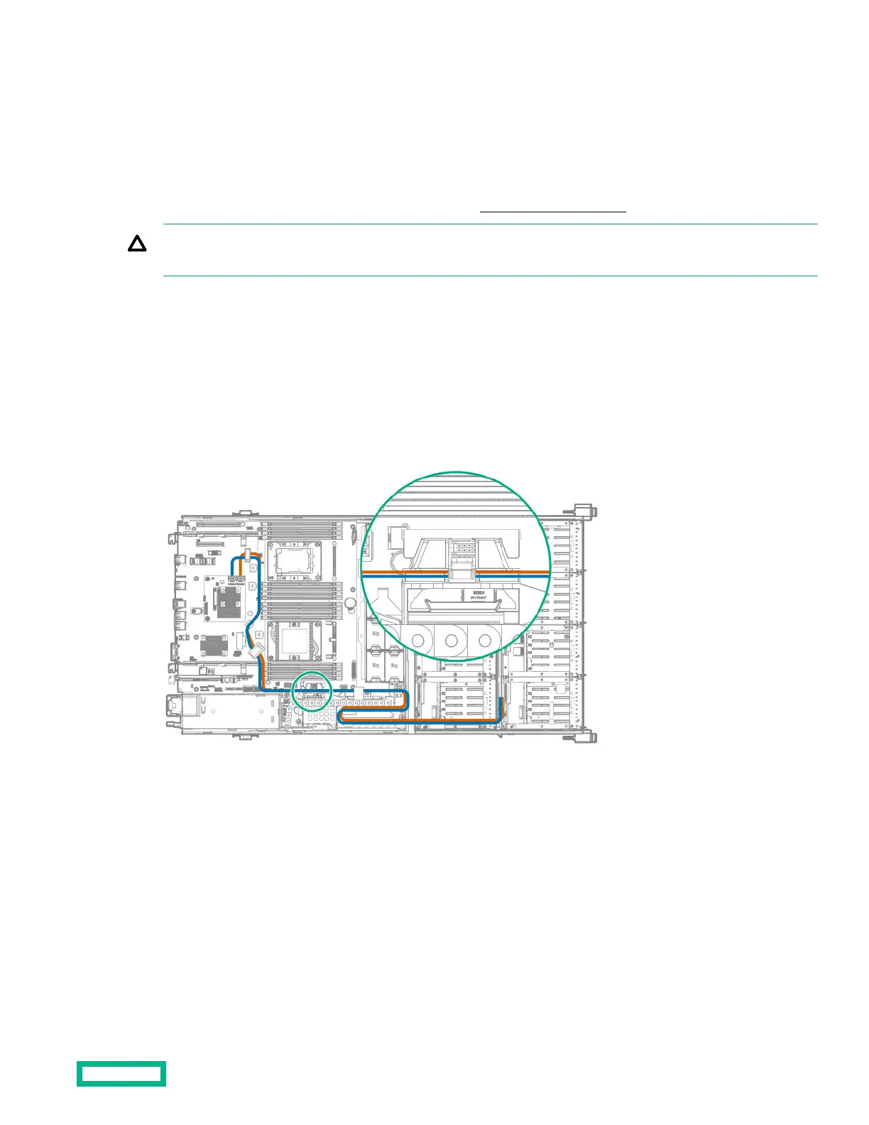
Front drive cage cabling
• Front drive cage P1 and P2 cables connected to P1 and P2 on one of the following options installed on the system board:
◦ HPE Smart Array E208i-a SR Gen10 controller
◦ HPE Smart Array P408i-a SR Gen10 controller
◦ HPE Smart Array P816i-a SR Gen10 controller
Front and internal drive cage cabling
• Front drive cage P1 and internal drive cage P1 connected to P1 and P2 on an HPE Smart Array E208i-a SR Gen10
controller or an HPE Smart Array P408i-a SR Gen10 controller installed on the system board
Cabling
123
 Loading...