8. Remove the drive backplane.
To replace the component, reverse the removal procedure.
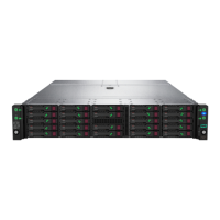
Removing and replacing the LFF drive cable track assemblies
The Mini SAS and power cables used in the 24-bay LFF front drive cages are enclosed in two plastic cable track assemblies.
The top cable track connects to the front LFF drive cage backplane; the bottom cable track connects to the internal LFF drive
cage backplane.
WARNING: To reduce the risk of personal injury from hot surfaces, allow the drives and the internal system components
to cool before touching them.
CAUTION: To prevent damage to electrical components, take the appropriate anti-static precautions before beginning
any installation, removal, or replacement procedure. Improper grounding can cause electrostatic discharge.
Prerequisites
Before you perform this procedure, make sure that you have the components included with the hardware kit.
Removal and replacement procedures
99
 Loading...