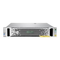
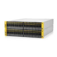
Figure 8: Power button on disk enclosure
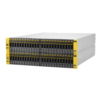
SAS cabling to disk enclosures
The following example shows the disk enclosure installed above the server and connected to the RAID
controller card in Slot 2. There is a 1U support shelf above the head server to protect it from the weight of the
disk enclosures. This is the installation that is described in the printed StoreOnce 5500 Start Here poster.
1
2
3
4
1
5
6
4
4
1
iLO
PS2
PS1
D1D2
IOM A
IOM B
IOM A
IOM B
P2
P1
P2
P1
P2
P1
P2
P1
P1P2
Figure 9: Cabling between head server, PCIe slot 2, and bundled enclosure
From To
Drawer 2, IO module A, port 1 Drawer 1, IO module A, port 2
Drawer 2, IO module B, port 1 Drawer 1, IO module B, port 2
RAID card in PCI slot 2, port 1 Drawer 1, IO module A, port 1
RAID card in PCI slot 2, port 2 Drawer 2, IO module B, port 2
32 SAS cabling to disk enclosures
 Loading...