6. To use communication to start/stop and to set running frequency
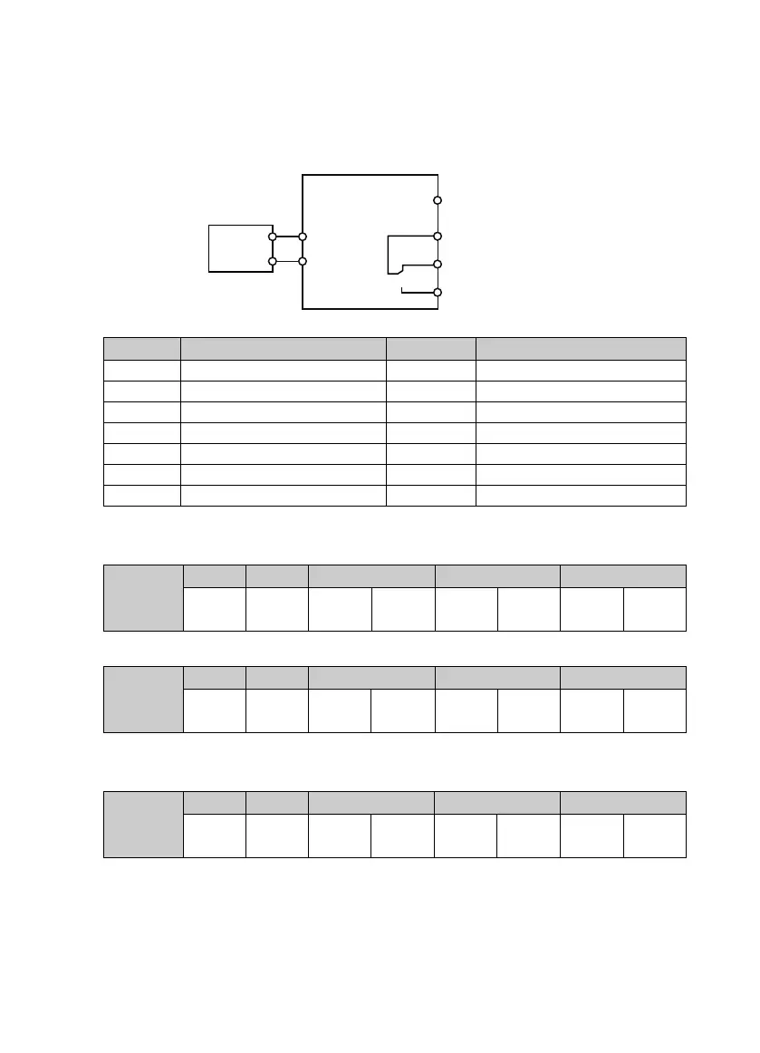
1. Wire communication lines as following:
2. Power on, and set function parameters according to connection.
Ref. code Function Setting Meaning
F00.10 To select frequency setting channel 2 SCI setting
F00.11 To select command setting channel 2 Running command channel set by SCI
F03.01 Acc. time 1 - Acc. time, adjust according to actual
F03.02 Dec. time 1 - Dec. time, adjust according to actual
F17.00 Data format 0 (default) 1-8-2 format, no parity, RTU
F17.01 Baut rate 3 (default) 9600bps
F17.02 Local address 2 (default)
3. Register 0x3200 of SCI communication (code 0x06) starts/stops inverter whose local address = 2.
E.g: Forward start command is as following:
Command /
Response
Frame
Address Code Register address Register content Checksum
0x02 0x06 0x32 0x00 0x10 0x01 0x4B 0x41
E.g: Dec stop command is as following:
Command /
Response
Frame
Address Code Register address Register content Checksum
0x02 0x06 0x32 0x00 0x10 0x04 0x8B 0x42
4. Register 0x3201 of SCI communication (code 0x06) sets the running frequency.
E.g: Set the running frequency of local address = 45.00Hz:
Command /
Response
Frame
Address Code Register address Register content Checksum
0x02 0x06 0x32 0x01 0x11 0x94 0xDB 0x7E
Fault indicating
Output indicating
signal at running
DO1
R1C
R1B
R1A
A
B
PLC
485+
485-

 Loading...

