Shenzhen Hpmont Technology Co., Ltd. Chapter 6 Function Introduction
HD3N Series User Manual V1.1 - 87 -
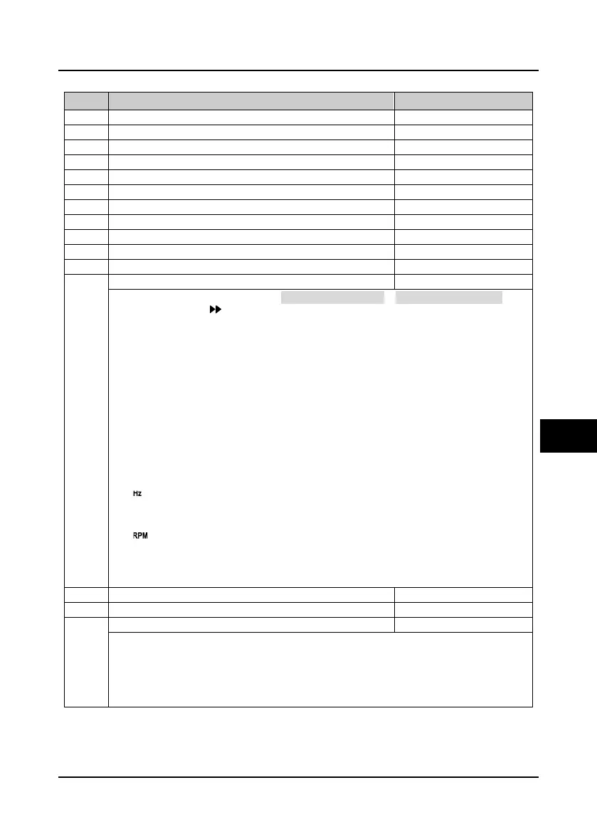
6.2.16 F18: Display Control Parameter
Ref. code Function Description Setting Range [Default]
Set parameter 1 of run status
Set parameter 2 of run status
Set parameter 3 of run status
F18.05 Set parameter 4 of run status 0 - 49 [13]
Set parameter 5 of run status
Set parameter 6 of run status
Set parameter 1 of stop status
Set parameter 2 of stop status
Set parameter 3 of stop status
F18.11 Set parameter 4 of stop status 0 - 49 [22]
Set parameter 5 of stop status
Set parameter 6 of stop status
The keypad displayparameters which is the run status (F18.02 - F18.07) or stop status (F18.08 - F18.13). It can
be cycling displayed by key on the keypad.
0: Unuesd.
1: Rated current of HD3N.
3: Invertre status.
• Refer to d00.10.
4: Main setting frequency
channel.
5: Main setting frequency.
6: Aux setting frequency.
7: Setting frequency.
8: Setting frequency (after Acc. /
Dec.).
9: Output frequency.
• flashes during running.
10 Setting Rpm.
11: Running Rpm.
• flashes during running.
12: Input cable voltage.
13: Output voltage.
14: Output current.
15: Torque setting.
16: Output torque.
17: Output power.
18: DC busbar voltage.
19: Input voltage of
potentionmeter.
20: AI1 input voltage.
21: AI1 input voltage (after
calculating).
22: AI2 input voltage.
23: AI2 input voltage (after
calculating).
28: DI6 terminal pulse input
frequency.
29: AO1 output.
30: AO2 output.
31: High speed output pulse
frequency.
32: Heatsink temperature.
33: Setting line speed.
34: Reference line speed.
37: Process PID setting.
38: Process PID feedback.
39: Process PID deviation.
40: Process PID integral value.
41: Process PID output.
42: External counting value.
43: Input terminal status.
• Bit0 - Bit5 corresponds to DI1
- DI6.
44: Output terminal status.
• Bit0 - Bit2 corresponds to
DO1, DO2 and RLY1.
45: MODBUS status.
46: Actual length.
47: Accumulative length.
48: Total time at power on (hour).
49: Total running time (hour).
Display accuracy of line speed
0: Round number.
1: One decimal.
2: Two decimals.
3: Three decimals.
Note: Once set F18.16, re-set F18.15.

 Loading...

