Shenzhen Hpmont Technology Co., Ltd. Chapter 6 Function Introduction
HD3N Series User Manual V1.1 - 49 -
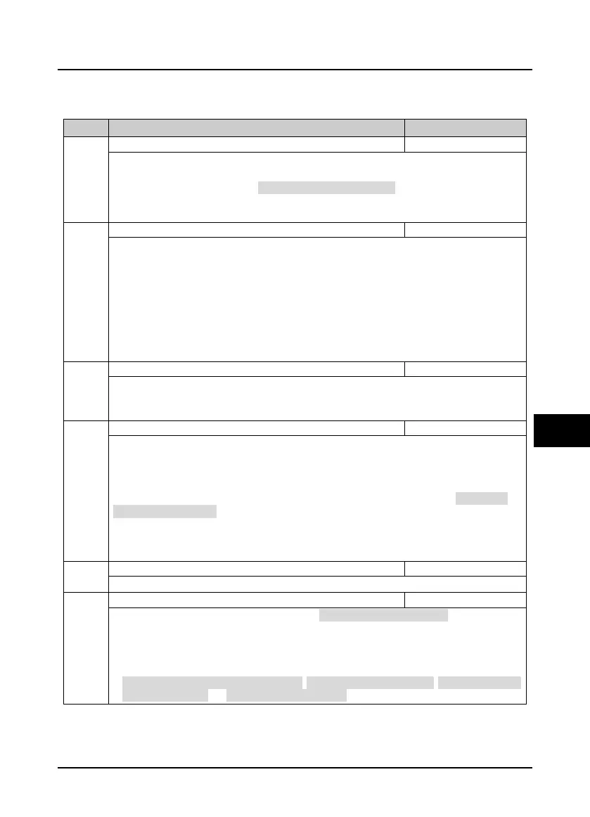
6.2 Group F: General Parameters
6.2.1 F00: Basic Parameters
Ref. code Function Description Setting Range [Default]
0: Speed control.
1: Torque control.
• Torque control is valid only when motor control mode = 2 (F00.01 = 2).
• Refer to group F15 DI terminal (No. 56/57 function) for detail description of torque control and group
F21 for torque control parameter.
0: V/f control without PG. Constant control voltage/frequency rate.
• It is applicable for occasions when one inverter drives more than one motors to achieve proper
efficiency.
• When select V/f control, please properly set the V/f control Group F09 to achieve proper efficiency.
2: Vector control without PG. (SVC control)
• It is applicable for application with high requirement on inverter performance and torque.
• At first, it must perform motor parameter auto-tuning. And then adjust the settings of F08.00 - F08.04
according to the nameplate of the motor. Start the motor parameter auto-tuning function and
properly set Group F10 parameters, so as to achieve excellent vector control efficiency.
Max. output frequency of HD3N
Defines the max. frequency that HD3N is allowed to output.
• V/f: max. 400Hz; Vector control: max. 200Hz.
• Please set F00.06 according to nameplate of motor and actual running conditions.
Upper limit of running frequency setting channel
Defines the max. frequency that system is allowed to run, and use F00.07 to select setting channels to set
the upper limit frequency.
0: Digital setting. Set the upper limit frequency by F00.08.
1: Analogue input setting. Refer to Group F16.
2: Terminal pulse setting. Set by F16.17, and its max. pulse input frequency corresponds to F00.06 (max.
output frequency of HD3N).
3: AI1.
4: AI2.
7: Potentionmeter. Valid when LED keypad adopted only.
Upper limit of running frequency
F00.07 = 0, the upper limit frequency is set by F00.08.
Lower limit of running frequency
Use F00.09 to limit the actual output frequency. When Zero frequency threshold (F19.10)
<
setting
frequency
<
F00.09, HD3N will run at lower limit frequency.
• Properly set F00.09 according to the nameplate of the motor and actual running conditions.
• No limitation on the motor parameter auto-tuning function.
• Besides the lower /upper limit frequency, the running frequency of inverter is also limited by
starting/stop DWELL frequency (F02.02, F02.14), zero frequency threshold (F19.10), starting frequency of
stop DC brake (F02.16) and skip frequency (F05.17 - F05.19).

 Loading...

