Shenzhen Hpmont Technology Co., Ltd. Chapter 4 Electrical Installation
HD3N Series User Manual V1.1 - 19 -
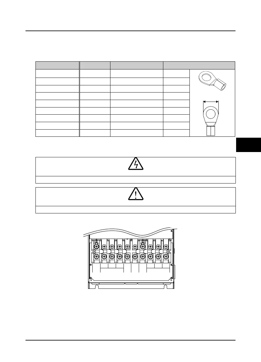
4.2.2 Power Terminal Lug
Select the lug of power terminal according to the size of terminal, screw size and max. outer diameter
of lug. Refer to Table 4-3. Take the TNR terminal as an example.
Table 4-3 Selection of power terminal lug
Size Screw size Tightening torque (N. M) Max. outer diameter d (mm)
Frame 3 M4 1.2 - 1.5 10.2
Frame 4 M5 2.3 - 2.5 12.3
Frame 5 / 6 M6 4.0 - 5.0 17.0
Frame 7 M8 9.0 - 10.0 20
Frame 8 M10 17.6 - 22.5 30
Frame 9 M12 31.4 - 39.2 37
Frame 10 M12 31.4 - 39.2 40
Frame 11 M12 31.4 - 39.2 40
Frame 12 M16 48.6 - 59.4 40
4.3 Main Circuit Terminals and Wiring
The bare portions of the power cables must be bound with insulation tapes.
Ensure that AC supply voltage is the same as rated input voltage of HD3N.
4.3.1 Supply and Motor Terminal
Frame 3 - Frame 7 supply and motor terminal
L1 L2
L3
WV
U
PE
(+) (-)
BR
POWER MOTOR

 Loading...

