Shenzhen Hpmont Technology Co., Ltd. Chapter 4 Electrical Installation
HD3N Series User Manual V1.1 - 21 -
Table 4-4 Supply and motor terminal description
HD3N
• L1, L2, L3: Three-phase AC power input terminals
• U, V, W: Output terminals, connect to three-phase AC motor
• (+), (-): DC supply input terminals; connect to braking unit
• (+), BR: Connect to braking resistor
PE: Ground terminal, connect to the ground
4.3.2 Supply and Motor Connection
During trial running, make sure HD3N runs forward when the forward command is enabled.
If not, switch any two of the output terminals (U/V/W) or modify F00.17 to change the motor direction.
The supply and motor connection are shown as Table 4-5.
Refer to section 4.2 Peripheral Accessories Selection (on page 17) for product options.
Refer to section 8.2 Braking Unit and Braking Resistor (on page 109) for braking resistors and braking
units.
Refer to section 8.3 Reactor Selection (on page 110) for reactor.
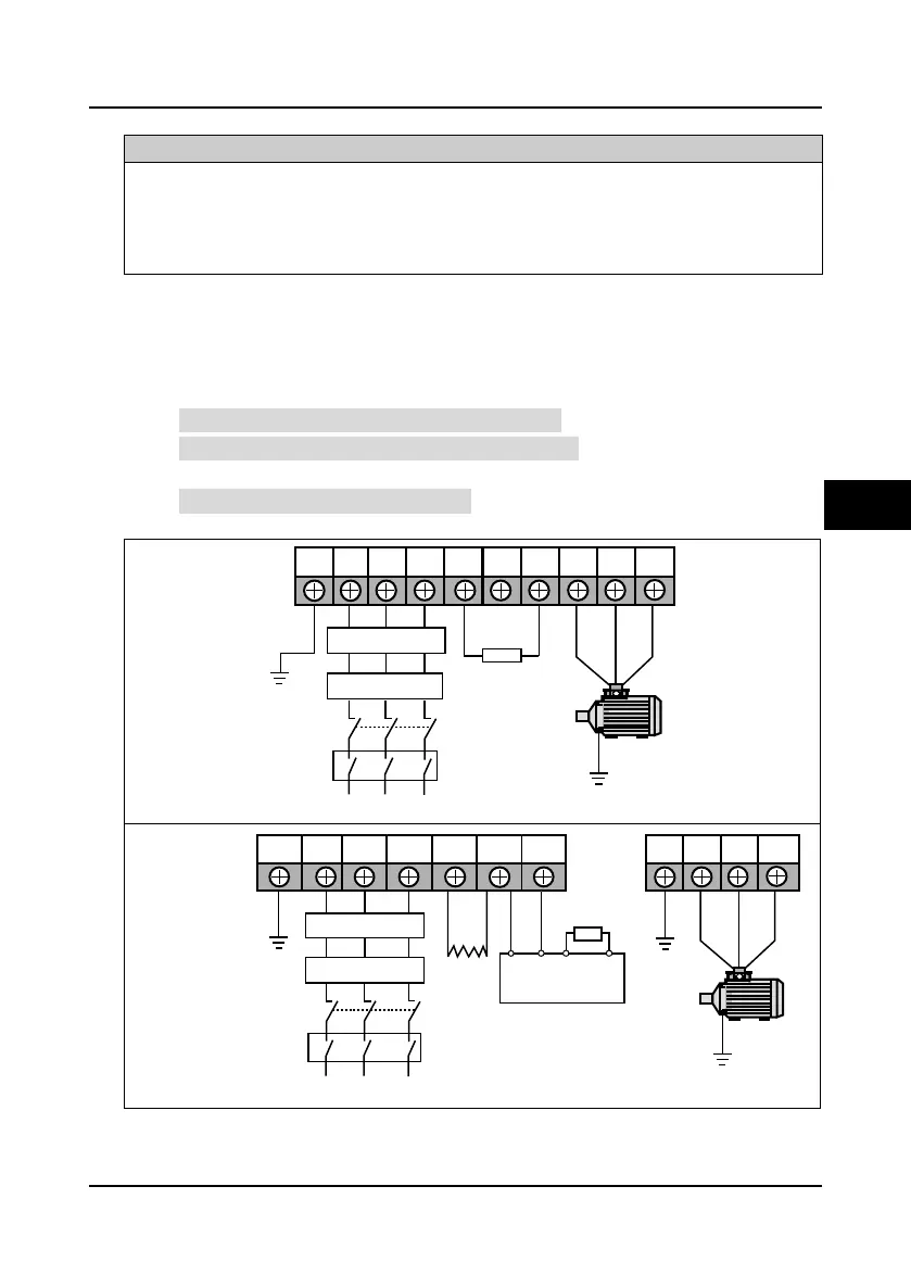
Table 4-5 Supply and motor connection
Frame 3 -
Frame 7
Frame 8 -
Frame 9
L1 L2 L3 (+) (-) BR U V WPE
Braking
resistor
Supply
ground
EMI filter
AC reactor
Mains supply
MCCB
Contactor
L1 L2 L3 (+) (-)PE
Braking
resistor
Supply
ground
P1
DC
reactor
U V WPE
Braking unit
BR1 BR2
(+)
(-)
Supply
ground
EMI filter
AC reactor
Mains supply
MCCB
Contactor

 Loading...

