Chapter 4 Electrical Installation Shenzhen Hpmont Technology Co., Ltd.
- 22 - HD3N Series User Manual V1.1
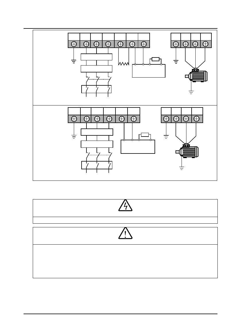
Frame 10 -
Frame 11
(including -C)
Frame 12
(including -C)
4.4 Control Board
• The control circuit and power circuit are basically insulated. Do not touch HD3N after it is powered.
• If the control circuit is connected to the external devices with live touchable port, it should increase an additional
isolating barrier to ensure that classification of external devices not be changed.
• If connect the communication terminal of the control circuit to the PC, choose RS485/232 isolating converter
which meets the safety requirement.
• Only connect the relay terminal to AC 220V voltage signal. Other control terminal are strictly forbiden for this
connection.
L1 L2 L3 (+) (-)
PE
Braking
resistor
Supply
ground
P1
DC
reactor
U V WPE
Braking unit
BR1 BR2
(+)
(-)
Supply
ground
EMI filter
AC reactor
Mains supply
MCCB
Contactor
L1 L2 L3 (+) (-)PE
Braking
resistor
Supply
ground
Supply
ground
U V WPE
Braking unit
Note: The DC reactor is built-in
BR1 BR2
(+)
(-)
EMI filter
AC reactor
Mains supply
MCCB
Contactor

 Loading...

