Chapter 6 Function Introduction Shenzhen Hpmont Technology Co., Ltd.
- 58 - HD3N Series User Manual V1.1
Ref. code Function Description Setting Range [Default]
Characteristic time of S curve at end of dec
Refer to figure in F03.00.
F03.15/F03.16 define the Acc. / Dec. time during jog running.
Define dec time for EMR stop.
6.2.5 F04: Process PID Control
Both analogue setting and feedback or pulse setting and feedback can form closed loop. Generally PID
is used for physical control, such as pressure, water level and temperature.
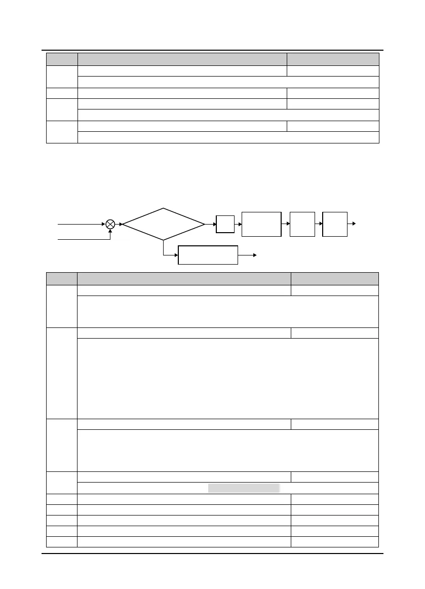
Below is the process:
Ref. code Function Description Setting Range [Default]
F04.00 Process PID control selection 0,1 [0]
0: PID control is disabled.
1: PID control is enabled.
Note: Set F04.00 = 0 when using aux PID.
F04.01 Setting channel selection 0 - 7 [0]
0: Digital. Set by F04.03.
1: Analogue. Set by analogue input voltage. Max. analogue input corresponds to 100% of PID setting, refer
to group F16.
2: Terminal pulse. Set the terminal pulse input. Max. input pulse frequency corresponds to 100% of PID
setting, refer to group F16.
3: AI1.
4: AI2.
7: Potentionmeter. Valid when LED keypad adopted only.
F04.02 Feedback channel selection 0 - 7 [0]
0: Analogue.
1: Terminal pulse.
2: AI1.
3: AI2.
6: Potentionmeter. Valid when LED keypad adopted
only.
7: Speed closed-loop.
F04.03 Setting digital reference -100.0 - 100.0 [0.0%]
Define the setting of PID regulator. Valid when F04.01 = 0 (digital setting).
F04.04 Proportional gain (P1) 0.0 - 500.0 [50.0]
F04.06 Integral upper limit 0.0 - 100.0 [100.0%]
F04.08 Differential upper limit 0.0 - 100.0 [20.0%]
Closed loop
regulation
PID
Limiting
control
Output
filtering
+
-
Deviation error
< Deviationerror
limit
Given quantity
Feedback quantity
N
Y
No PID process
adjustment
Output
Keep the last PID adjustment result

 Loading...

