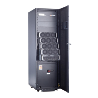
Item Specications
30 kVA 60 kVA 90 kVA 120 kVA
Ground
cable
Recommende
d cross-
sectional area
(mm
2
)
PE 10 16 35 50
● When selecting, connecting, and routing power cables, follow local safety
regulations and rules.
● When the external conditions change, for example, the cable layout or
ambient temperatures, perform
verication in accordance with the
IEC-60364-5-52 or the local regulations.
● If the rated voltage is 400 V, multiply the currents by 0.95. If the rated voltage
is 415 V, multiply the currents by 0.92.
● When the primary loads are non-linear loads, increase the cross-sectional
areas of the neutral wires 1.5–1.7 times.
● The nominal battery discharge current refers to the current of forty 12 V
batteries at 480 V in standard
conguration.
● The maximum battery discharge current refers to the current when forty 12 V
batteries in standard conguration, that is, two hundred and forty 2 V battery
cells (1.67 V/cell), stop discharging.
● When the mains input and bypass input share a power source,
congure input
power cables as mains input power cables. In addition, cables listed in Table
3-2 apply only to the following conditions:
– The cables are installed along the wall or on the
oor (IEC-60364-5-52 C
standards).
– The ambient temperature is 30°C.
– The AC voltage loss is less than 3%, and the DC voltage loss is less than
1%. The recommended cable diameters in Table 3-2 meet the basic
through-current requirements. Users should evaluate the line voltage loss
based on the actual cable length. If the voltage loss exceeds the
requirements, increase the cable diameter properly.
– Single- or multi-core 90°C-resistant copper
exible cables are used.
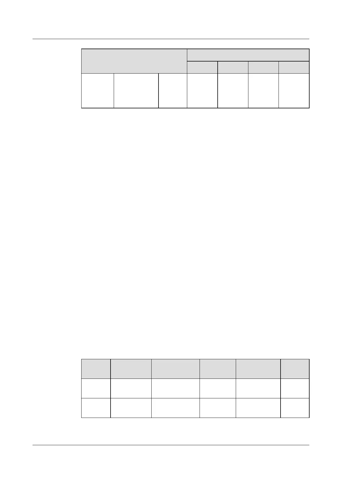
Table 3-3 Power cable terminal requirements
Port
Connection
Method
Bolt
Specications
Bolt Hole
Diameter
Bolt Length Torque
Mains
input
Crimped OT
terminals
M10 11 mm 30 mm 26 N·m
Bypass
input
Crimped OT
terminals
M10 11 mm 30 mm 26 N·m
UPS5000-E-(30 kVA–120 kVA)-FM
User Manual 3 Installation
Issue 03 (2022-01-30) Copyright © Huawei Technologies Co., Ltd. 50
 Loading...