e-4 MAX200 Instruction Manual
3-96
APPENDIX E – ELECTROMAGNETIC COMPABILITY (EMC)
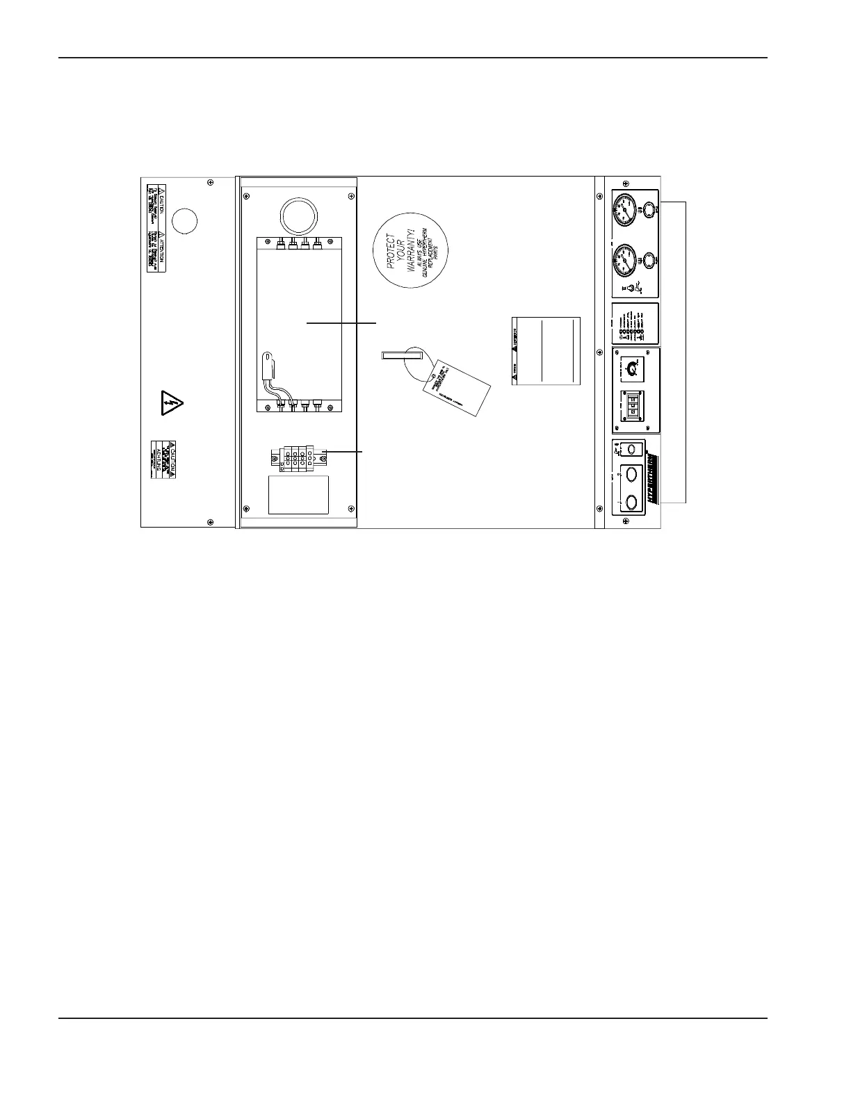
2. Unscrew the four filter cover screws and remove cover to access input voltage connections at TB1 (see
Figure e-2).
3. Insert the power cable through the strain relief (see Figure e-1).
4. Connect leads L1 to U, L2 to V, and L3 to W terminals of TB1 (see Figure e-3). Ensure that all connections are
tight to avoid excessive heating.
5. Connect the ground lead to terminal marked PE at TB1 (see Figure e-3).
Figure e-2 MAX200 Power Supply with EMI Filter Cover Off – Top View
TB1
Filter