3-10 MAX200 Instruction Manual
1-97
SETUP
Power, Gas, Torch Lead, and Torch Connections
Connecting the Power Cable
To connect the power cable to the 400V CE power supplies (073200 and 073213), refer to
Appendix E. For other power supply voltages use the procedure below.
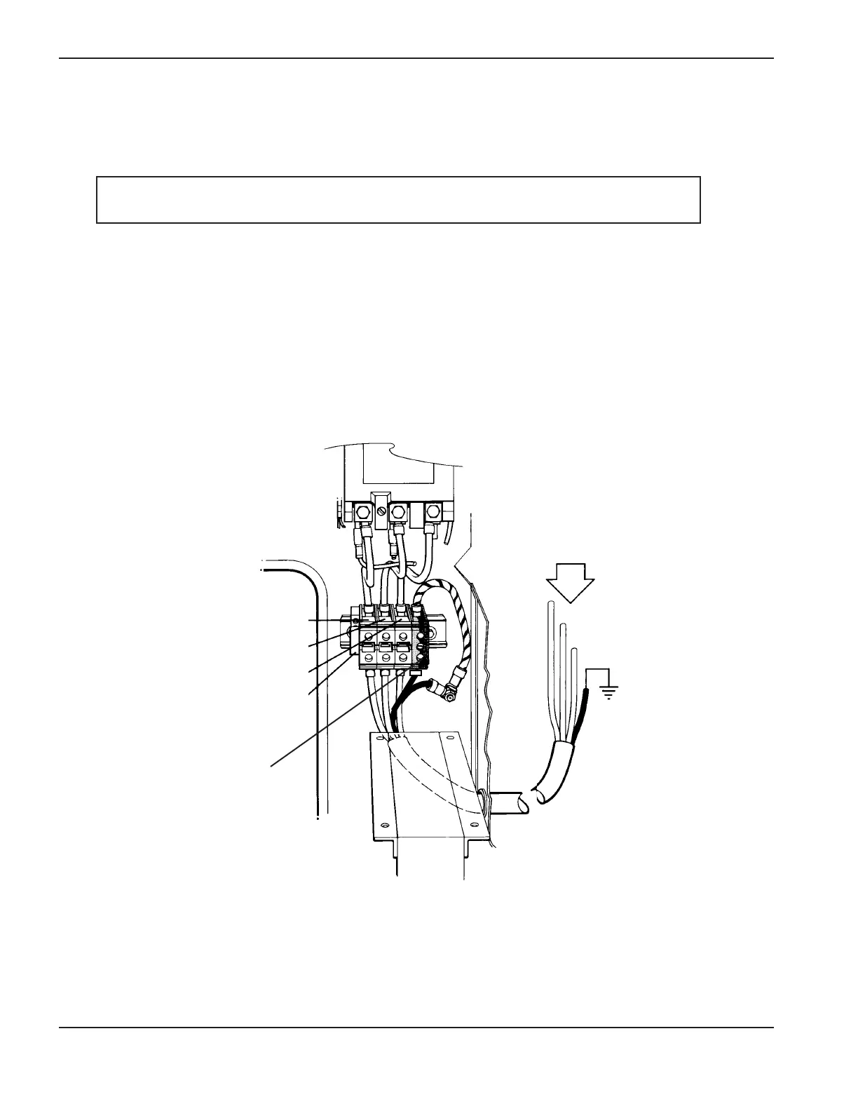
To connect the power cable to the MAX200, proceed as follows (see Figure 3-3):
1. Insert the power cable through the strain relief at the rear of the MAX200.
Connect the power cable leads to TB1 located at the rear center panel of the right side.
2. Connect the power leads to the L1, L2, and L3 terminals of TB1.
3. Connect the ground lead to the yellow/green terminal of TB1.
Figure 3-3 Power Cable Connections