MAX200 Instruction Manual e-5
APPENDIX E – ELECTROMAGNETIC COMPABILITY (EMC)
Line Disconnect Switch
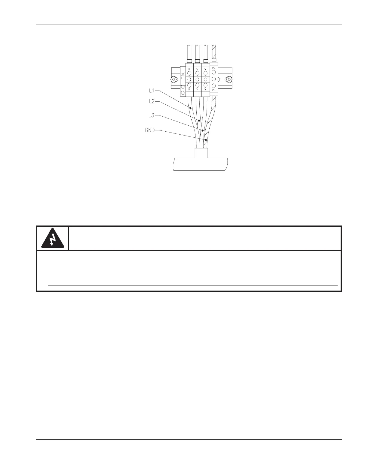
Connecting the power cable to the line disconnect switch must conform to national or local electrical codes. This
work should be performed only by qualified, licensed personnel. See Power Requirements and Line Disconnect
Switch on page 3-6.
Figure e-3 Power Cable Connections to TB1
WARNING
The neon light attached to the line filter will turn ON as soon as the line disconnect switch is ON. This
indicator is a warning that there is line voltage at the filter even if the ON (1) pushbutton on the
MAX200 power supply has not been pressed. As a common safety practice, ALWAYS verify that the
line disconnect switch is in the OFF position before installing, disconnecting or servicing in this area.