MAX200 Instruction Manual 7-1
15
Section 7
WIRING DIAGRAMS
Introduction
This section contains the wiring diagrams for the MAX200 system. When tracing a signal path or referencing with
the Parts List or Troubleshooting sections, please be aware of the following format to assist you in understanding
the wiring diagrams' organization:
• Sheet numbers are located in the lower right-hand corner.
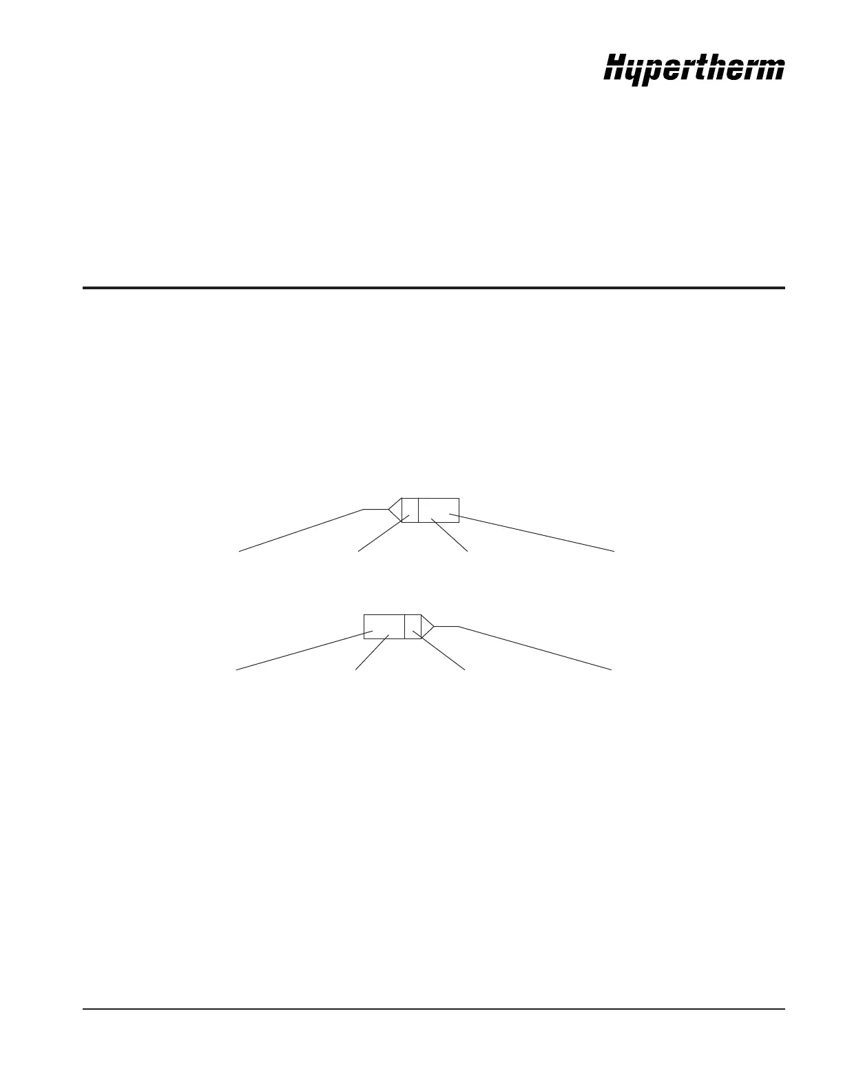
• Page-to-page referencing is done in the following manner:
C
SHEET
4-D3
C
SHEET
4-D3
Destination and Source Coordinates refer to letters A-D on the Y-axis of each sheet and numbers 1-4 on the
X-axis of each sheet. Lining up the coordinates will bring you to the source or destination blocks (similar to a road
map).
Wiring Diagram Symbols
Wiring diagram symbols and their identification precede the system wiring diagrams in this section.
Source Connection Source Reference Block Destination Sheet # Destination
Coordinates
Source Sheet # Source Coordinates Source Reference Block Destination
Coordinates