92 D0559 Rev. A SlideDriver/SlideDriver 50VF Series www.hysecurity.com
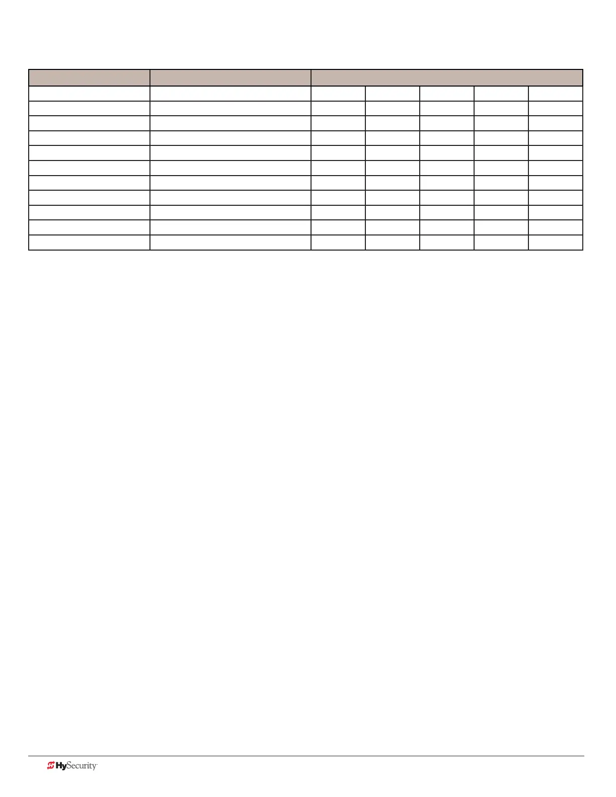
slIdedrIver operator maIntenanCe sCHedule
Name of part What to do Check at these recommended monthly intervals
1 3 6 12 24
Gate and hardware Check for damage and wear *1 X
Drive wheels Check for tightnes and wear *2 X
Wheel clamp spring Check for clamping tension *3 X
Stop limit switches Check for adjustment *4 X
Deceleration switches Check for adjustment *4 X
Anchor bolts Check for tightness X
Fluid level Check for loss of uid *5 X
Hydraulic uid Drain and replace uid X
Clock battery Replace *6 X
Motor Brushes (DC Only) Replace *7 X
Special Notes:
*1. Your gate and gate hardware will require more maintenance than your HySecurity operator. A damaged gate or worn hardware
may cause slow or erratic operation and will result in excess drive wheel wear. Lubricate gate hardware more frequently and
check for smooth operation by opening the toggle clamping mechanism and then pushing the gate manually. One person
should easily be able to push all but the largest of gates. Damaged or warped gate panels should be straightened or replaced.
*2. Normally, drive wheel life is many years. They are designed to avoid slipping on the rail. Wheels may be greatly shortened by
any of these faults: clamping spring not adjusted correctly, operator misaligned in relation to gate panel, badly warped gate
panel, extremely stiff gate hardware, and/or loose wheel mounting bolts (tighten to 25 ft. lb).
*3. Verify that the red clamping spring is compressed tightly so that drive wheels apply a strong grip on drive rail. The red spring
should normally be compressed to 2-inches in height. See 87.
*4. The limit switch and deceleration switch rollers should ride ¼ to ½-inch below the drive rail, near the center of the channel.
Maladjustment may result in false or early tripping or no limit function at the end of travel. Verify that the limit trip ramps are
tightly bolted to the drive rail.
*5. The uid level should remain no less than one inch below the ller hole. Refer to maintenance instructions for uid lling. Loss
of uid is not normal and indicates a leak that must be located and repaired. Use Uniow uid, part MX000970, if additional
uid is required.
*6. Replace the Smart Touch Controller coin battery with DL 2025 / DL 2032 or CR 2025 / CR 2032.
*7. DC Operators use DC motors with 4 carbon brushes which wear in normal operation. Worn brushes can damage the DC
motor. Under severe conditions HySecurity recommends that brushes be checked after 2 years or 250,000 cycles and the
replacement interval be adjusted as necessary.
 Loading...