www.hysecurity.com Power D0559 Rev. A 15
1. Connect to Power: Three wires and a ground are available for connection to a 3 Phase power source
(3Ø). Loosen the screws on the power module to open the wire slots at the top and bottom.
2. Connect AC Power: Place the incoming power wires into their appropriate slots. Attach the ground wires
to the chassis. A wiring diagram is provided in the appendix.
CAUTION
Wiring of gate operators must conform to NFPA and NEC standards and
comply with all local codes. When the installation is compliant and complete,
turn on AC power at the source and at the control box.
Turning the Power Switch ON
The AC power disconnect switch is located on the same enclosure
(control box) where the electrical components, Smart Touch
Controller, transformer, power module, etc., are found.
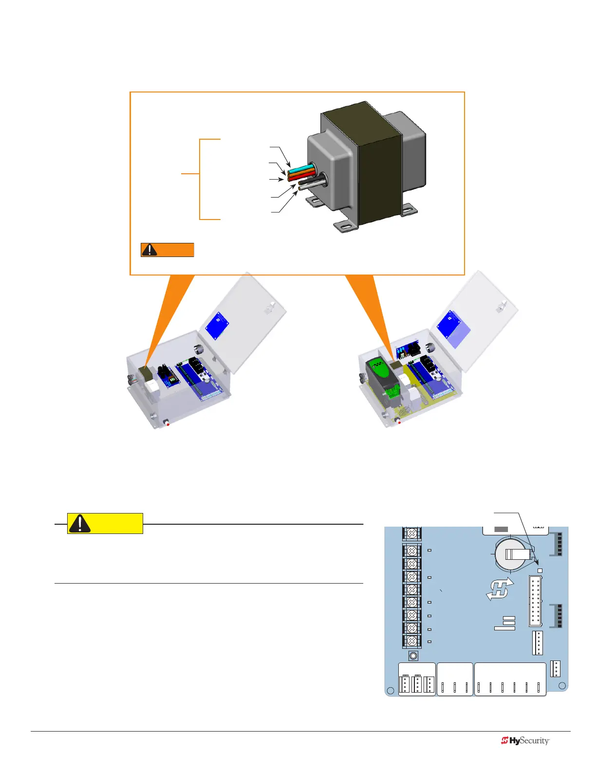
When power is turned ON, a green status light on the Smart Touch
Controller blinks. The status light appears below the coin battery and
indicates that the processor is receiving power. For more information,
refer to “Smart Touch Controller Inputs” on page 52.
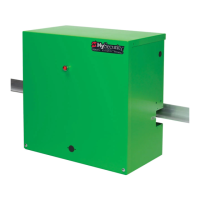
Input taps
Blue - 480 VAC
Orange - 240 VAC
Red - 208 VAC
Black - Common
White - 120 VAC*
Control Transformer
All (Excluding SD50VF) SD50VF - series
* Variable Frequency (VF) or 2 hp gate operators:
Never connect to the white 120V wire. Make sure the
connection wires match the voltage found on the operator’s nameplate.
Green LED ashes indicating
processor is receiving power.
DO NOT USE
PHOTO EYE
OPEN DIRECTION
DO NOT USE
PHOTO EYE
CLOSE DIRECTION
DO NOT USE
CHARGER
AC LOSS
LOCK INTERLOCK
EMERG CLOSE
FIRE DEPT OPEN
16
17
18
19
20
21
22
23
24
Smart Touch Controller
LIMIT DUAL GATE
RADIO OPTIONS
VEHICLE DETECTOR
SHADOW
RESET
WIEGAND
HySecurity
MX000585
VERSION
S/N
RS232
DISPLAY
VEHICLE DETECTOR
COM COMA B
RPM
COMOPEN EDGE+24V +24V
STAT U S
LED
 Loading...