www.hysecurity.com STC Inputs & Wiring D0559 Rev. A 55
user relaYs – programmIng proCedure
The Smart Touch Controller is able to interface with many types of
external devices through the use of three user programmable output
relays: two mechanical relays (User 1 and User 2), and one solid state
relay (User 3) which is used most often for connection to ashing
devices.
All of the user relay functions identied and described in the table
below are accessible in the Installer Menu
(R1 x, R2 x, R3 x) selections.
NOTE: A setting of zero disables a User Relay. The User Relays will operate normally to 18VDC. Below 18VDC,
alert notication occurs. On Crash products User 3 relay is unavailable. It is pre-wired for the LED lights.
Use the STC buttons to program the user relays according to the following steps:
1. Select the relay you wish to use through the Installer
Menu: Table 2 on page 42. For example:
R1 13 (RELAY LOGIC 1) or R2 15 (RELAY LOGIC 2).
2. Select the appropriate function (1 through 28) by
changing the display to the associated number listed in
the table. Use the Select, Next and Previous buttons to
make your selection. Refer to Menu Mode Navigation on
page 36.
Programmable User Relays: Table 3
Setting Performance Description Wire
Connection
1 Close limit output Output can be used as an interlock signal to another
operator’s interlock input, or simply to indicate that the gate
is secure. The relay is “off” when the gate is closed. The relay
energizes when the fully-closed limit is released. (Any open
command energizes the relay.)
Relay 1, 2 or 3
2 Close limit pulse output Used in a sequenced system to command a second machine
to close. Generates a brief pulsed output that occurs when
the close limit is triggered.
Relay 1, 2 or 3
3 Open limit output Indicates a full-open position. This output becomes active
when an open-limit is triggered and deactivates when the
open-limit is released or a close command is received.
Relay 1, 2 or 3
4 Open limit pulse output Used in a sequenced gate system to command a second
machine to open. Generates a brief pulsed output that
occurs when the open limit is triggered.
Relay 1, 2 or 3
5 Warn before/during operate output Controls an external warning device. This output operates at
the same time as the internal warn before operate buzzer.
Relay 1, 2 or 3
6 Gate Lock output Controls external solenoid or magnetic locks. In both
directions of travel, this output is activated about 7/10ths of
a second before the operator starts moving the gate and
remains active while moving. Output remains active, for a
few seconds, after stopping.
Relay 1, 2 or 3
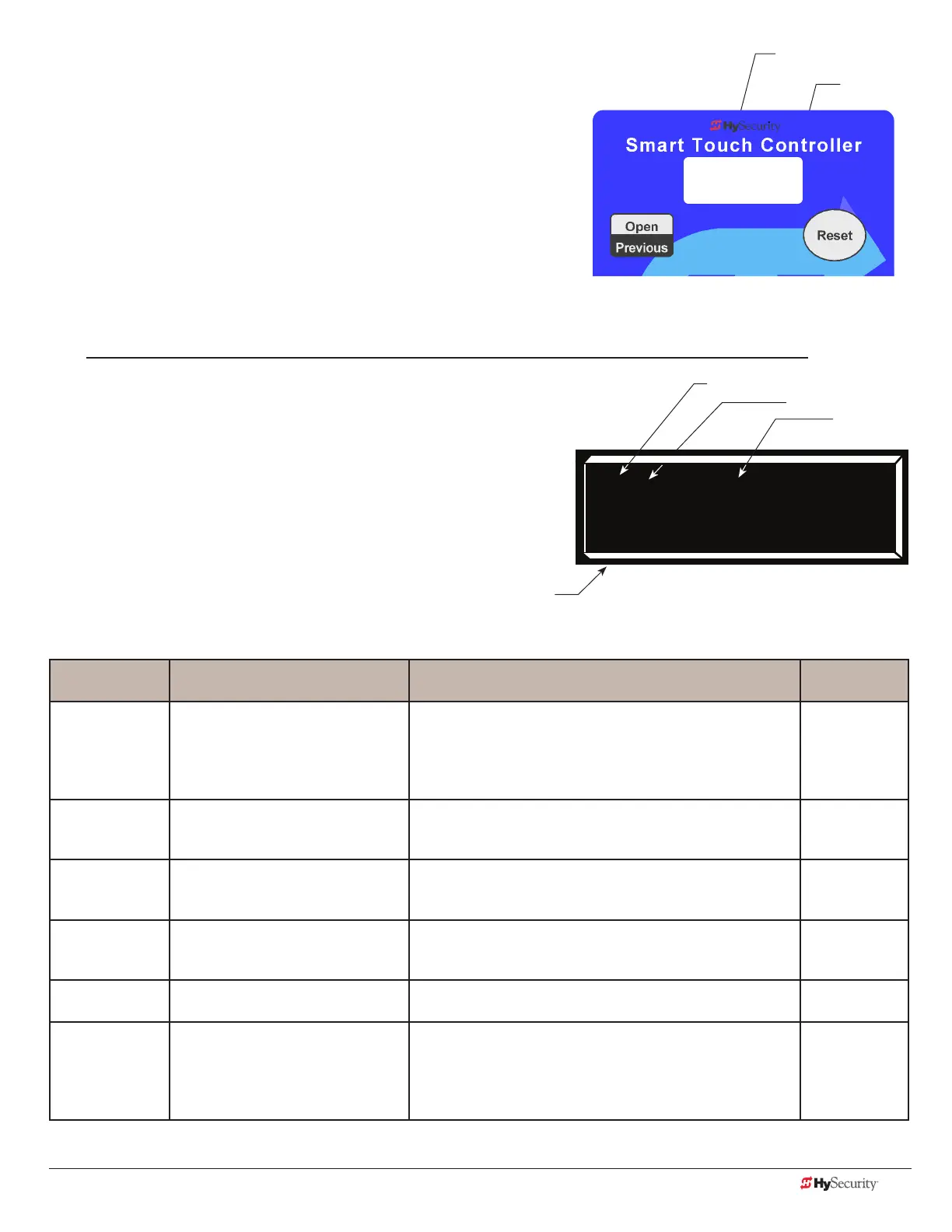
R1 1 CLOSE LIM
RELAY 1 LOGIC
STC display (32 character OLED)
Identies relay number
Setting
Performance
Description
Identies relay number
Setting
STC display (7-segment)