60 D0559 Rev. A SlideDriver/SlideDriver 50VF Series www.hysecurity.com
Four vehicle detector inputs (terminals: 8, 10, 11, and 12) exist on the Smart Touch Controller, as well as the four
direct plug ins for the HY-5A modules. Refer to Overview of the STC and Power Module on page 50.
The vehicle detector input functions are as follows:
• Free Exit Loop Detector - Opens a fully closed gate.
• Outside Obstruction Loop Detector (Out Obs Loop) - Triggered by the outside (public side) vehicle
detector loop
• Inside Obstruction Loop Detector (In Obs Loop) - Triggered by the inside (secure side) vehicle detector
loop
• Center/Reset/Shadow Loop Detector - On barrier arm gates, prevents closure when active. On swing
gates, prevents gate from opening or closing when the vehicle detector is active.
NOTE: Use of any combination of HY-5A detectors and box detectors is acceptable. On occasion, multiple
obstruction detectors may be mandatory. For example, an area greater than 200 square feet (61 square meters)
of vehicle loop cannot be connected to any one detector because the sensitivity becomes inadequate.
ConneCtIng HY-5a veHICle deteCtors
NOTE: Refer to the installation instructions provided with the HY-5A vehicle detectors. It provides detailed
illustrations and instructions that are not found in the steps below.
A quick overview on how to install the HY-5A Vehicle Detector modules, one at a time, follows:
1. Turn off the AC power switch on the Control Box.
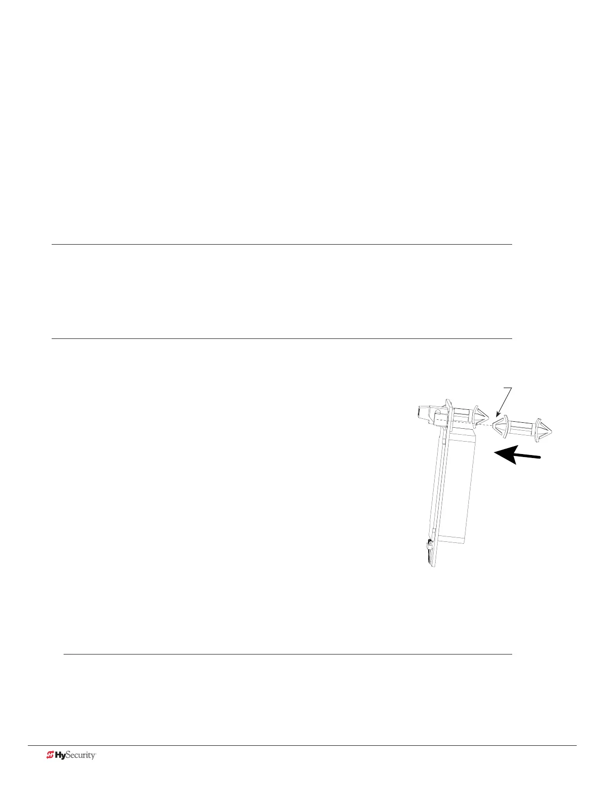
2. Insert the locking end of the two white plastic standoffs into the
mounting holes on the detector.
3. Plug the detector into the appropriate socket along the right
edge of the Smart Touch Controller. Be careful to align the six
detector pins into the socket correctly (the screws for tightening
the terminals should face toward the board), and then snap the
standoffs into the holes in the control box.
4. Route the loop wires through the holes provided in the control
box and connect the loop leads to the two terminals on the HY-5A
detector. Tighten the terminal screws securely.
5. To enable the detector, turn on power. The detector will
immediately tune if it is connected to a vehicle loop. Make sure no
cars or other metal objects are over the loop.
6. Repeat Steps 1 through 5 for each HY-5A detector.
7. If the detector module is unplugged after it is enabled, a communications alert (ALERT 10) will be
triggered. If the fault is not resolved, an error message, ERROR 3 “Detector Failed” is displayed.
NOTE: If there is any detector fault, the gate operator functions as if the detector is triggered.
Squared off end of
standoff
 Loading...