54 D0559 Rev. A SlideDriver/SlideDriver 50VF Series www.hysecurity.com
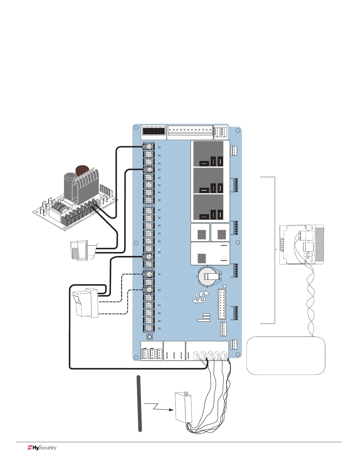
ConneCtIng aCCessorY devICes
Devices, such as gate edge sensors and photoelectric beams, must be installed to protect against entrapment.
These secondary entrapment protection devices are required for the gate installation to be in compliance with
UL 325 Safety Standards. NOTE: Always check your local area codes and comply with all regulations.
Standard accessory (entrapment and loop wire) connections are shown in the following illustration. All accessories
require a minimum of two connections:
• a device input
• a Common Bus Terminal (COM)
STOP BUTTON
OPEN BUTTON
CLOSE BUTTON
REMOTE OPEN AND
RADIO CONTROL
OPEN/CLOSE
1
OPEN PARTIAL
INTERLOCK OPEN
TIME CLOCK OPEN
FREE EXIT DETECTOR
DISABLE EXIT DETECTOR
DISABLE CLOSE TIMER
INSIDE OBSTRUCTION
VEHICLE DETECTOR
OUTSIDE OBSTRUCTION
VEHICLE DETECTOR
SHADOW/RESET
VEHICLE DETECTOR
EDGE SENSOR
PHOTO EYE POWER
24 VOLTS COMMON
PHOTO EYE POWER
DO NOT USE
PHOTO EYE
OPEN DIRECTION
DO NOT USE
PHOTO EYE
CLOSE DIRECTION
DO NOT USE
CHARGER
AC LOSS
LOCK INTERLOCK
EMERG CLOSE
FIRE DEPT OPEN
2
3
4
5
6
7
8
9
10
11
12
14
15
16
17
18
19
20
21
22
23
24
Smart Touch Controller
LIMIT DUAL GATE
RADIO OPTIONS
DRIVE
POWER
RS485
MOTOR USER 1
USER 2
USER 3
VEHICLE DETECTORVEHICLE DETECTORVEHICLE DETECTOR
STOP/BUZZER
FREE
EXIT
INSIDE
OBSTR
OUTSIDE
OBSTR
SHADOW
RESET
WIEGAND
HySecurity
COM
NO
MX000585
VERSION
S/N
RS232
DISPLAY
VEHICLE DETECTOR
COM COMA B
RPM
COMOPEN EDGE+24V +24V
STAT US
LED
24V
A
C A
cce
s
s
or
y powe
r
+
24
V
D
C
Power Connector
HY-5A
FREE EXIT
HY-5A
INSIDE LOOP
HY-5A
OUTSIDE LOOP
HY-5A
CENTER LOOP
LOOP
Not to Scale
C
O
MM
ON
HY-5A
Two wires
attach to COM.
Conguration
depends on
whether AC or DC
powered.
Installer menu settings:
PC 0 = Normally Open
PC 1 = Normally Closed*
(*PC 1 is monitored photo eye)
Photo eye:
4-wire connection:
+24V
PHOTO EYE POWER (STC)
COM (Power module)
PHOTO EYE OPEN or CLOSE
(depending on function)
Photo eye
Access controls
(Ex. Card reader, keypad_
Power Module
Edge
sensor
2 channel
radio receiver
 Loading...