www.hysecurity.com STC Inputs & Wiring D0559 Rev. A 53
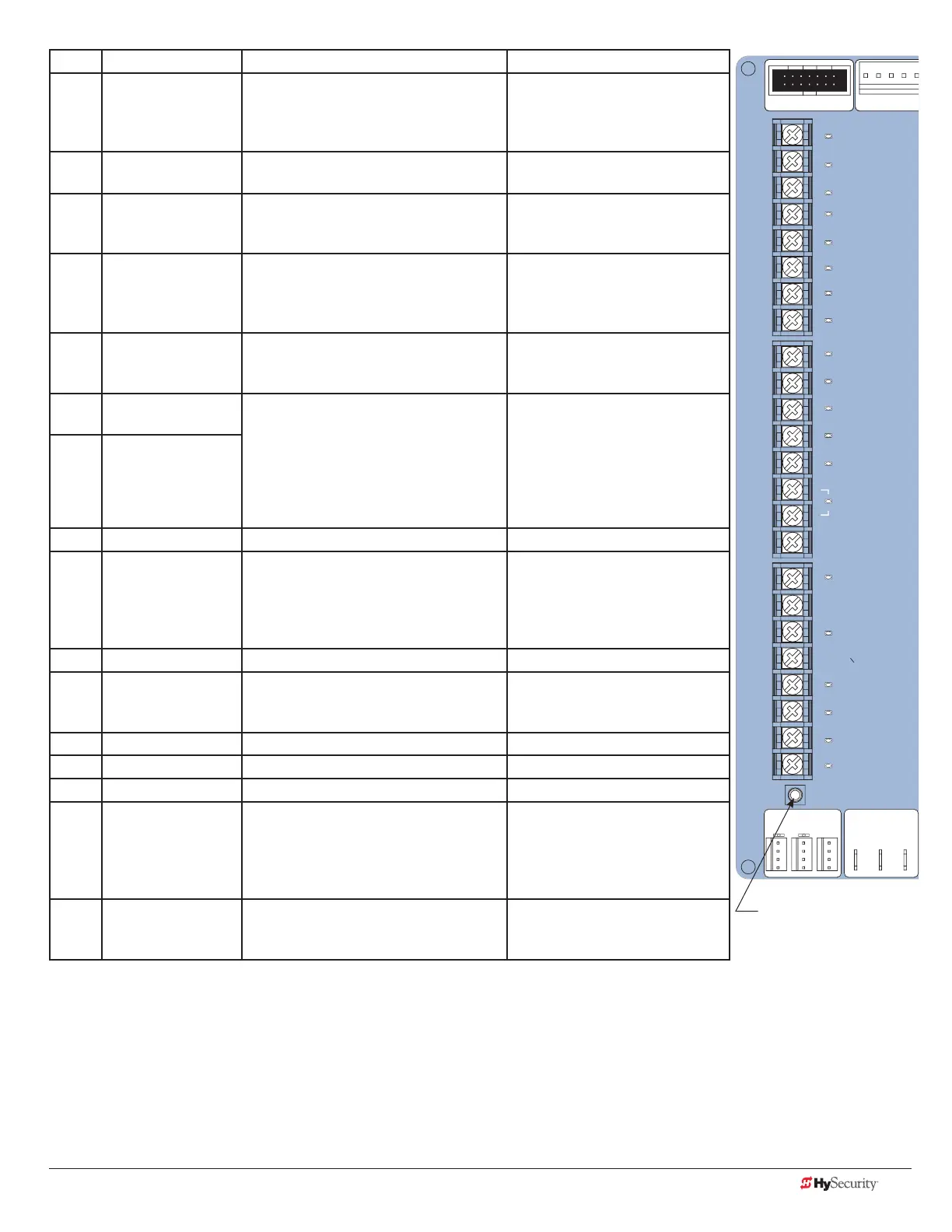
No. STC Terminal Wire Connections Commonly used for...
9 Disable Exit
Detector/Disable
Close Timer
Free Exit is only disabled if the Close
Limit Switch is tripped. If the gate is
partially opened, the Free Exit detector
will trigger the gate to open fully.
Connection to free exit loop.
Installer menu enabled. Refer to
DT 0.
10 Inside Obstruction
Vehicle Detector
Refer to the Installer Menu: Table 2 on
page 42.
Vehicle detector, box type
connections inside reversing loop
11 Outside Obstruction
Vehicle Detector
Refer to CR 0 in the Installer Menu: Table
2 on page 42.
Vehicle detector, box type
connections outside reversing
loop
12 Shadow/Reset
Vehicle Detector
Refer to CR, CB, and CP in the Installer
Menu: Table 2 on page 42.
Vehicle detector, box type
connections. Shadow function
for swing gates, reset function for
barrier arm gates.
13 Edge Sensor Refer to GC in the Installer Menu: Table
2 on page 42.
Gate edge, entrapment device
sensor connections. One input
works for both travel directions.
14 Photo Eye Power
(-) 24 Volts Common
If photo eyes are used in place of vehicle
detector loops, connect 24V Common
to Power Supply COM & connect NO
output to appropriate vehicle loop
detector input: Terminals 8, 10, 11 or 12.
Refer to Photo Eyes (Non-Contact)
Installation on page 61.
Photo eye open and close
connections.
15 Photo Eye Power
(-) 24 Volts Common
16 DO NOT USE
17 Photo Eye Open Refer to EO and PC in the Installer
Menu: Table 2 on page 42.
NOTE: Input disabled in HydraLift,
StrongArm and CRASH barrier arm
operators.
Photo eye open connection.
Connect NO or NC to Terminal
17 & COM where entrapment is a
concern such as the storage area
along a slide gate fence line.
18 DO NOT USE
19 Photo Eye Close Refer to EC and PC in the Installer
Menu: Table 2 on page 42.
If photo eye close connection
spans road: Connect NO or NC
output to Terminal 19 & COM.
20 DO NOT USE
21 Charger AC Loss Connection from battery cabinet. DC battery type operators only.
22 Gate Lock Interlock Refer to user relay option 23. Locking mechanisms.
23 Emergency Close Activate with +24. Refer to OC setting in
the Installer Menu: Table 2
on page 42.
Installer menu enabled and
input +24V to trigger. Requires
constant hold or supervised
input. Overrides photo eyes,
gates edges & vehicle detectors.
24 Fire Dept Open Jumper to +24. Refer to the Installer
Menu: Table 2 on page 42.
Installer menu FO enabled and
input +24V to trigger. Overrides
photo eyes and gates edges.
STOP BUTTON
OPEN BUTTON
CLOSE BUTTON
REMOTE OPEN AND
RADIO CONTROL
OPEN/CLOSE
1
OPEN PARTIAL
INTERLOCK OPEN
TIME CLOCK OPEN
FREE EXIT DETECTOR
DISABLE EXIT DETECTO
DISABLE CLOSE TIMER
INSIDE OBSTRUCTION
VEHICLE DETECTOR
OUTSIDE OBSTRUCTIO
VEHICLE DETECTOR
SHADOW/RESET
VEHICLE DETECTOR
EDGE SENSOR
PHOTO EYE POWER
24 VOLTS COMMON
PHOTO EYE POWER
DO NOT USE
PHOTO EYE
OPEN DIRECTION
DO NOT USE
PHOTO EYE
CLOSE DIRECTION
DO NOT USE
CHARGER
AC LOSS
LOCK INTERLOCK
EMERG CLOSE
FIRE DEPT OPEN
2
3
4
5
6
7
8
9
10
11
12
14
15
16
17
18
19
20
21
22
23
24
Smart Tou
LIMIT DUAL GATE
DRIVE
COMA B
RPM
LED
Tact Button
STC Inputs
 Loading...