SHADOW/RESET
VEHICLE DETECTOR
SENSOR 1
SENSOR COM
DO NOT USE
SENSOR 2
DO NOT USE
SENSOR 3
DO NOT USE
CHARGER
AC LOSS
LOCK INTERLOCK
EMERG CLOSE
FIRE DEPT OPEN
14
15
16
17
18
19
20
21
22
23
24
LIMIT DUAL GATE
COM
A B
RPM
LED
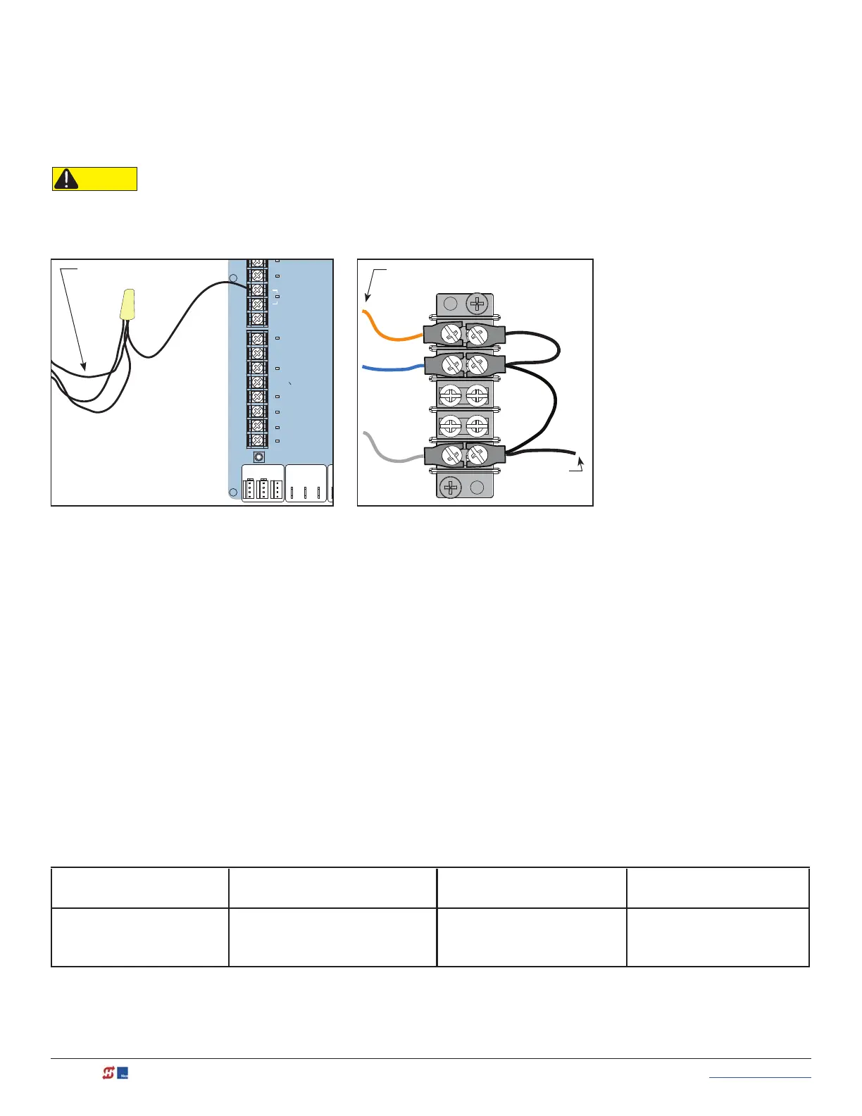
Wiring Tips for SENSOR COM Terminal: Smart
Touch
Two SENSOR COM terminals exist (Terminal 14 and Terminal 15). If using multiple sensor devices, use a wire
nut as a junction and pigtail to SENSOR COM. Or, install a separate terminal block and jumper outputs to one
Wires coming from
sensor device
CAUTION
All external entrapment protection sensors must be NC sensor outputs and wired to the SENSOR COM terminal for
monitoring and powering purposes. The sensor becomes actively powered when the gate operator receives a run command.
Wire nut and pigtail to SENSOR COM Add terminal block
Wires coming
from sensor
device
Wire to
SENSOR
COM
lead for either SENSOR COM terminal.
Menu Mode Navigational Tips
To access Menu mode, press the Menu button twice. The gate operator will not run while in Menu Mode. The
buttons on the display keypad perform certain functions while in Menu Mode. Refer to the chart.
To change data
appearing in the display
To navigate through
the Selections
To choose what appears
on the display
To navigate between
menu items
Press Select.
Two left characters blink.
Press Next or Previous.
Continue pressing Next to view
all selections.
Press Select.
Blinking characters
become static.
Press Next or Previous.
Advance - press Next
Previous - press Previous
NOTE: LEDs next to the sensor connections will be lit when NO POWER is being applied. To temporarily supply power to the
sensors. see See Photo Eye Alignment Feature on page 101. When PE is turned ON, the LEDs turn off. If they do not turn off, check
for wiring issues such as a short or misapplied relay COM connections. See Supply Power to the Sensors on page 43.
Connect
sensor's "Relay
COM"wiring
to Terminal 14
or 15
(SENSOR COM)
132 MX3630-01 Rev. J SlideDriver/SlideDriver 50VF Series © 2019 www.hysecurity.com