24V AC Acce
s
sory power
+
24
V
D
C
STOP BUTTON
OPEN BUTTON
CLOSE BUTTON
REMOTE OPEN AND
RADIO CONTROL
OPEN/CLOSE
1
OPEN PARTIAL
INTERLOCK OPEN
TIME CLOCK OPEN
FREE EXIT DETECTOR
DISABLE EXIT DETECTOR
DISABLE CLOSE TIMER
INSIDE OBSTRUCTION
VEHICLE DETECTOR
OUTSIDE OBSTRUCTION
VEHICLE DETECTOR
SHADOW/RESET
VEHICLE DETECTOR
SENSOR 1
SENSOR
COM
DO NOT USE
SENSOR 2
DO NOT USE
SENSOR 3
DO NOT USE
CHARGER
AC LOSS
LOCK INTERLOCK
EMERG CLOSE
FIRE DEPT OPEN
2
3
4
5
6
7
8
9
10
11
12
14
15
16
17
18
19
20
21
22
23
24
Smart Touch Controller
LIMIT DUAL GATE
RADIO OPTIONS
DRIVE
POWER
RS485
MOTOR USER 1
USER 2
USER 3
VEHICLE DETECTORVEHICLE DETECTORVEHICLE DETECTOR
STOP/BUZZER
FREE
EXIT
INSIDE
OBSTR
OUTSIDE
OBSTR
SHADOW
RESET
WIEGAND
HySecurity
COM
NO
MX000585
VERSION
S/N
RS232
DISPLAY
VEHICLE DETECTOR
COM COMA B
RPM
COMOPEN
S 1
+24V +24V
STAT US
LED
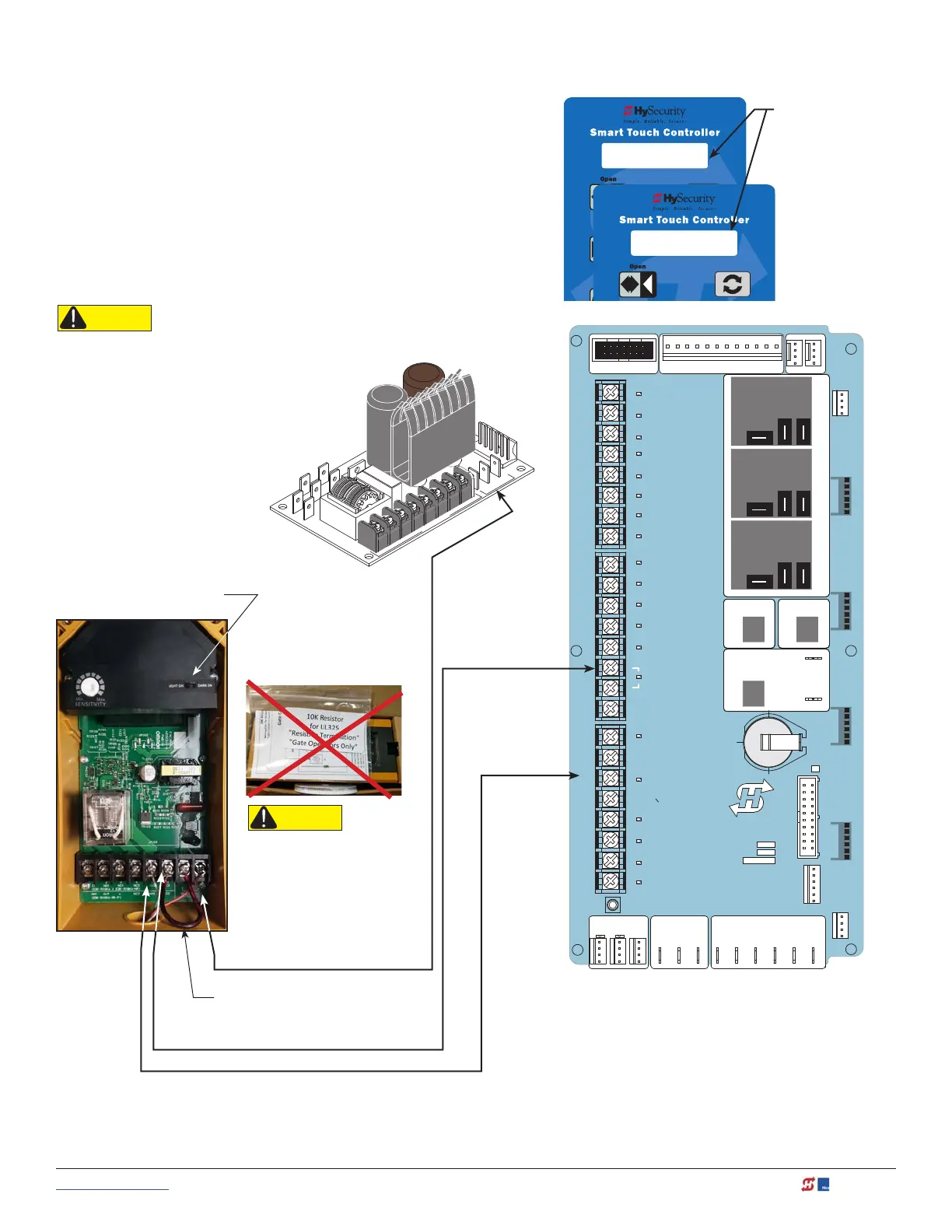
Smart Touch: Photo Eye / Reflective (E3K R10K4)
1. Set Photo Eye switch to LIGHT ON. See NOTE.
1. Connect photo eye wiring.
NOTE: Run a jumper between photo eye -24V and
Relay COM (C2) terminals. See photo.
2. Turn ON power.
3. Access the Installer Menu and congure SENSOR
setting according to the entrapment area that the
photo eye is monitoring. Refer to Table 4: Installer Menu
Settings for SENSOR Inputs on page 42.
S3 0
SENSOR #3 TYPE
S3 2 (EYE CLOSE)
SENSOR #3 TYPE
Installer Menu
showing Sensor 3 set
to Eye Close (Option
#2)
Omron (E3K R10K4)
Reflective Photo Eye
NOTE: Light/Dark switch
must be set to LIGHT ON.
+24V
Jumper -24V to Relay COM
(Terminal 6, C2)
Relay NO (Terminal 5, NO2)
COMMON / NEG. to SENSOR COM
Power Supply Board
NOTE: If you receive an Alert, "!ACTION
BLOCKED" "Photo Eye Open" PEO or "Photo
Eye Close" PEC, take steps to align the photo
eye. Refer to See Photo Eye Alignment Feature on
page 101.
CAUTION
All external entrapment protection sensors
must be NC sensor outputs and wired to the
SENSOR COM terminal for monitoring and
powering purposes. The sensor becomes
actively powered when the gate operator's
motor runs.
CAUTION
Do NOT connect the 10K
resistor to HySecurity
gate operators. Follow the
instructions on this sheet to
avoid FAULT 2.
www.hysecurity.com © 2019 Wiring HySecurity Sensors: Smart Touch MX3630-01 Rev. J 135