32 MX3630-01 Rev. J SlideDriver/SlideDriver 50VF Series © 2019 www.hysecurity.com
Adjusting the Pressure Relief Valve
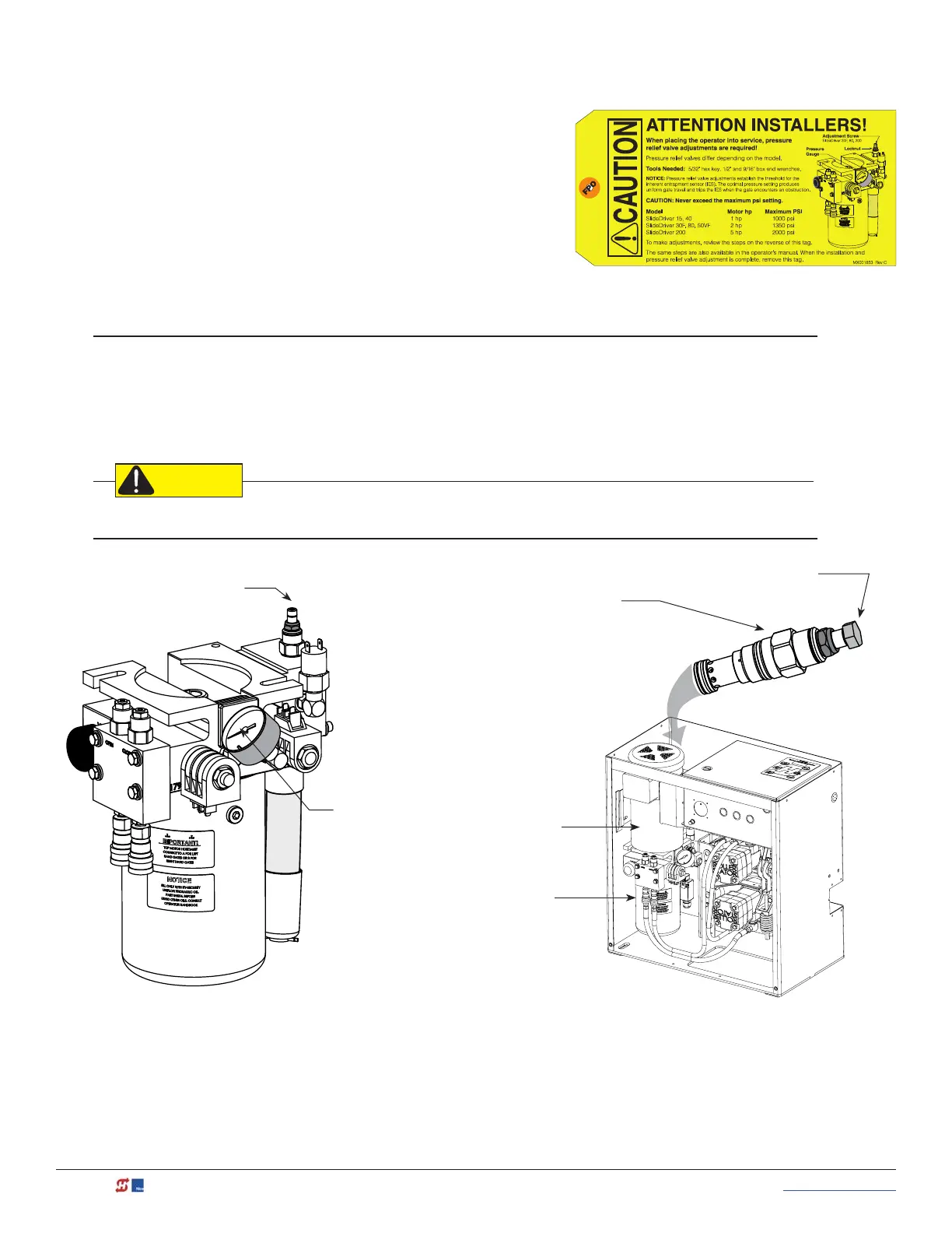
When placing the operator into service, pressure relief valve
adjustments are required! To provide instruction during
installation, a cautionary yellow tag is wire tied to every pump
pack. The same instructions are provided in this section.
Pressure relief valves differ depending on the model.
Tools Needed: 5/3 2 " hex key, ½" and 9/1 6 " box end wrenches.
NOTICE: Pressure relief valve adjustments establish the threshold for the inherent entrapment sensor (IES). The
optimal pressure setting produces uniform gate travel and trips the IES when the gate encounters an obstruction.
Model Motor hp Maximum PSI
SlideDriver 15, 40 1 hp 1000 psi
SlideDriver 30F, 80, 50VF 2 hp 1350 psi
SlideDriver 200 5 hp 2000 psi
Never exceed the maximum psi setting.
Hex socket adjustment screw
SlideDriver 30F, 80, 200
Pressure
Gauge
Motor
Pump
pack
Hex head adjustment screw
SlideDriver 15, 40, 50VF
The Pressure Relief
Valve is located
behind the motor
on the pump rack or
soft start manifold.