15
/
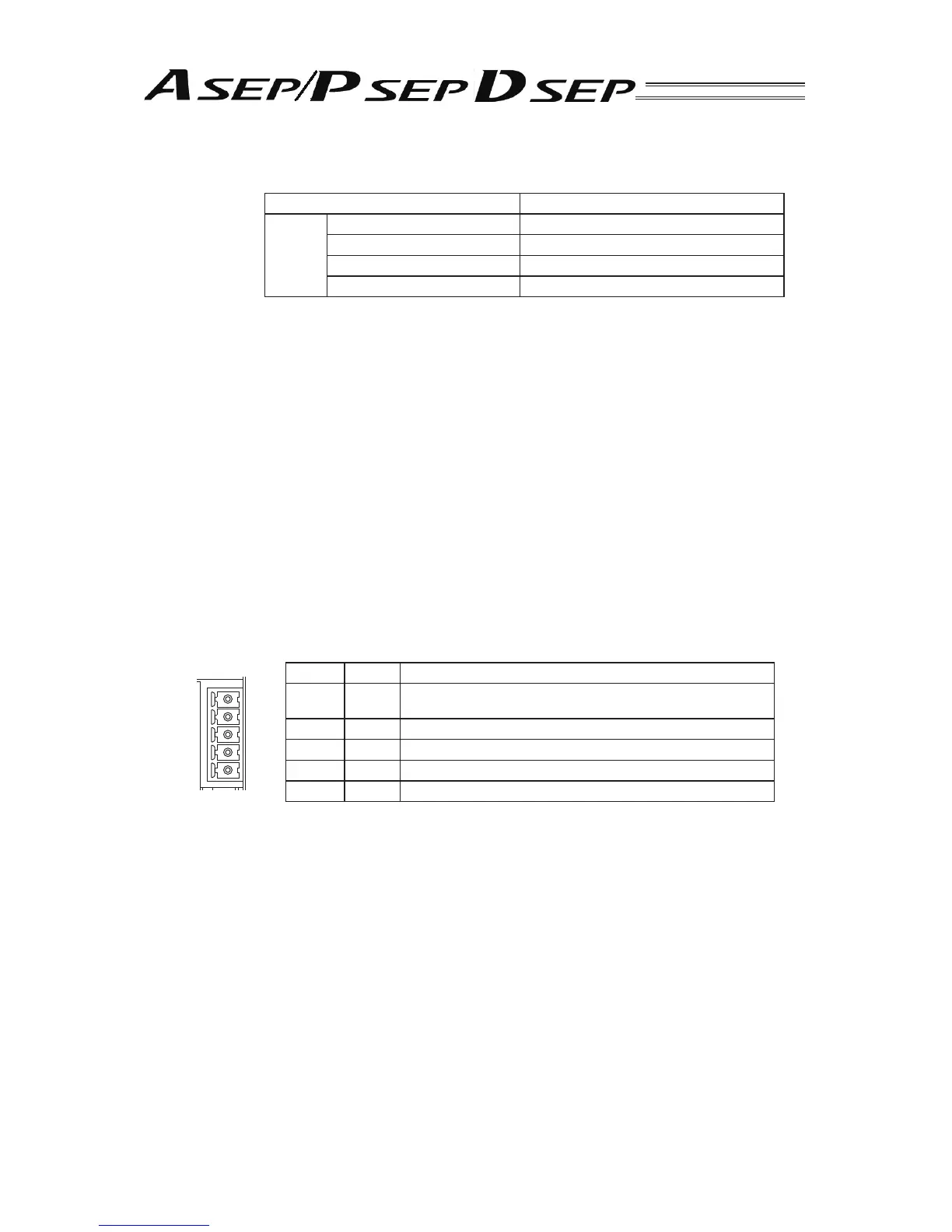
Pin No. Signal Description
5BK
For Brake Forced Release Power Supply (ASEP/PSEP)
Keep DSEP disconnected.
4 MP Motor Driving Power Supply
3 24V Positive side of the 24V power supply
2 0V Negative side of the 24V power supply
1 EMG EMG’s Confi rmation Signal
8) FG Terminal Block
It is the connector to connect the protection ground. Make sure to conduct the Class D grounding
(formerly Class 3 grounding: grounding resistance at 100
or less)
BK
MP
24V
0V
EMG
3) StatusLED (For SV, ALM and EMG)
Following show the controller operation status:
Indication Status Description
SYS
Green Light is turned ON. Servo ON Status
Light is turned OFF Servo OFF Status
Flashing in green (1Hz) Servo ON Status
Red Light is turned ON. In the alarm issue or emergency stop
4) SIO Connector
It is the connector for the connection of the communication cables for the teaching pendant and
PC software.
5) PIO Connector
It is the connector for 24V DC I/O signal connection.
6) Motor · Encoder Connector
It is the connector to connect the actuator motor · encoder cable.
7) Power Supply Connector
It is the connector to supply the power to the controller and to the control board.
 Loading...


