8.6 How to replace components
8-24
8. Maintenance and Inspection
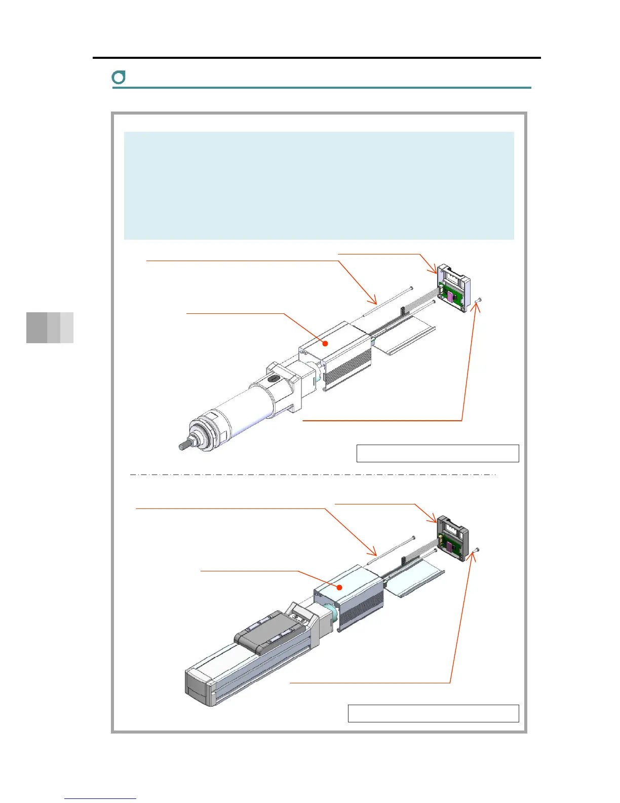
Wireless communication circuit board replacement
[EC-S6/S7/R6/R7/RR6/RR7]
(1) Loosen the screws, then remove the old end cover assembly.
(2) Loosen the screws, then dislodge the motor cover assembly.
Keep the cable connected to the motor cover assembly connected.
(3) Remove the cable connector for the old end cover assembly from the controller
circuit board inside the motor cover assembly.
→ For the connector location, refer to "Notes on connectors/wiring" (page 8-28).
Rod type replacement method
Slider type replacement method
Motor cover assembly
Cross-recessed tapping screws x 2 pcs
(M3 x 10, tightening torque 0.60N・m)
End cover assembly
Cross-recessed pan screws x 2 pcs
R6/R7: M3 x 110/150, tightening torque 0.60N・m
(M3 x 150/200 for models with brake)
Motor cover assembly
Cross-recessed tapping screws x 2 pcs
(M3 x 10, tightening torque 0.60N・m)
End cover assembly
Cross-recessed pan screws x 2 pcs
S6/S7: M3 x 110/150, tightening torque 0.60N・m
(M3 x 150/200 for models with brake)
(End cover assembly replacement)
 Loading...


